Regulating device for dc-dc converter and method for regulating dc-dc converter

A technology of DC voltage and regulating device, which is applied in the direction of converting DC power input to DC power output, converting device for output power, regulating electrical variables, etc.

Pending Publication Date: 2022-04-26
ROBERT BOSCH GMBH
View PDF2 Cites 0 Cited by
  • Summary
  • Abstract
  • Description
  • Claims
  • Application Information

AI Technical Summary

Benefits of technology

This patented technology describes a system called AC/DC converters (ACCs) which are used in electronic devices. These systems have multiple components connected through switches. Each component has its own unique characteristics, including ageing factors caused by environmental influences. To ensure proper functioning of all parts within the device, certain corrections should be applied individually beforehand. Additionally, some existing techniques involve storing corrected data separately from the original ones afterward. Overall, these technical improvements improve performance and efficiency of AC/VDCS's overall functionality.

Problems solved by technology

This patented technical problem addressed by this patents relates to improving efficiency when multiple converters work together with one another without overloading any other components or causing them to operate unevenly due to differences between their sizes.

Method used


Image

  • Regulating device for dc-dc converter and method for regulating dc-dc converter
  • Regulating device for dc-dc converter and method for regulating dc-dc converter
  • Regulating device for dc-dc converter and method for regulating dc-dc converter

Examples


Embodiment Construction

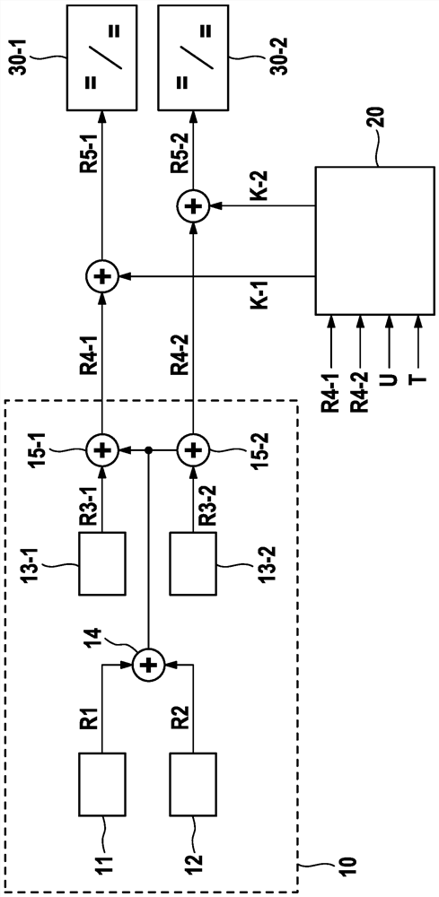
[0026] figure 1 A schematic diagram of a DC voltage converter 1 with a plurality of DC voltage converter modules 30-i is shown. The two direct voltage converter modules 30 - 1 and 30 - 2 shown here serve only as examples for a simple explanation of the basic principle of the invention. Of course, the DC voltage converter 1 can also have more than two DC voltage converter modules 30 - i.

[0027] The individual DC voltage converter modules 30-i are fed by a common input DC voltage. In addition, the output terminals of the respective DC voltage converter modules 30-i can also be connected to each other, so that the respective DC voltage converter modules 30-i also provide the same output voltage. In order to regulate the output voltage and the output current, the individual direct voltage converter modules 30 - i are each actuated with separate control variables R5 - i . For example, this can be an adjustment of the pulse width modulation, wherein the duty cycle of the adjustmen


PUM


Abstract

The invention relates to an extended adjustment of a control variable for a DC-to-DC converter having a plurality of DC-to-DC converter modules (30-1, 30-2). For this purpose, in addition to the conventional regulation of the individual DC voltage converter module, a further correction variable (K-1, K-2) is determined, which can be added to the regulation variable (R4-1, R4-2). The correction quantity can take into account in particular individual characteristics of the DC voltage converter module, such as component tolerances or the like. For this purpose, correction values suitable for the individual DC voltage converter modules can be determined beforehand and stored in a non-volatile memory. By using these previously stored relationships, the control variables for the individual DC voltage converter modules can be individually adjusted.

Description


Claims


Application Information

Patent Timeline
Owner ROBERT BOSCH GMBH
Why Eureka
Try Eureka