Projection lens, projection device and optically-induced microparticle device

A technology of projection lens and projection device, which is applied in the field of projection lens, and can solve problems such as complex projection optical path, inability to project all projection images into chips, and inability to view full-screen images in light-induced dielectrophoretic image imaging systems.

Active Publication Date: 2014-05-21
IND TECH RES INST
View PDF14 Cites 0 Cited by
  • Summary
  • Abstract
  • Description
  • Claims
  • Application Information

AI Technical Summary

Benefits of technology

The technical effect of this patented technology is that it allows for better understanding by showing different examples or illustrations related to each aspect of its function.

Problems solved by technology

The technical problem addressed by these inventions relates to improving the efficiency and accuracy of separating and analyzing biology samples like cancer cells from other parts of their body without damaging each part during processing procedures. Current methods are either slow down or require costly equipment.

Method used


Image

  • Projection lens, projection device and optically-induced microparticle device
  • Projection lens, projection device and optically-induced microparticle device
  • Projection lens, projection device and optically-induced microparticle device

Examples


Embodiment Construction

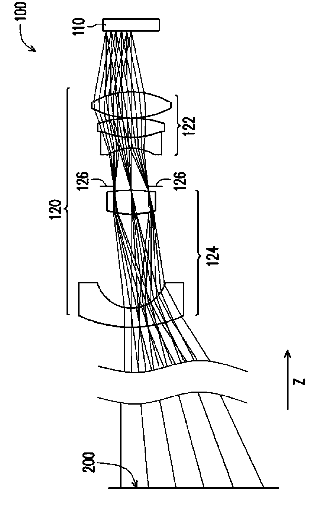
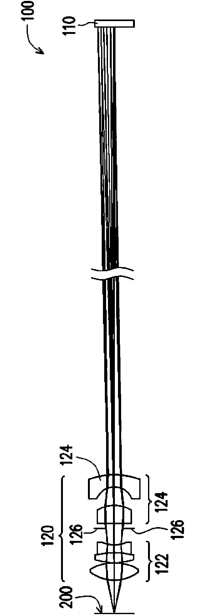
[0030] figure 1 is a schematic diagram of a projection device in a first state according to an embodiment of the present invention. figure 2 is a schematic diagram of a projection device in a second state according to an embodiment of the present invention. Please also refer to figure 1 and figure 2 , the projection device 100 of this embodiment is suitable for projecting an image of an object on a projection surface 200 to form an image frame. The projection device 100 includes an image unit 110 and a projection lens 120 . The image unit 110 is suitable for generating and displaying an image of an object. In this embodiment, the image unit 110 includes a liquid crystal display (liquid crystal display, LCD), a liquid crystal on silicon (LCOS) panel, a digital micro-mirror device (digital micro-mirror device, DMD) or an organic light emitting diode (organic light-emitting diode, OLED) and other components that can display images. The projection lens 120 is disposed on the


PUM


Abstract

A projection lens, a projection device and an optically-induced microparticle device are provided. The projection lens includes an aperture, a first and a second lens groups. The aperture, the first and the second lens groups are disposed on a projection path of an image. The aperture is between the first and the second lens groups. The first and the second lens groups are suitable for interchanging with each other to switch the magnification ratio. When in a first state, the first lens group is between the object and the aperture and the second lens group is between the aperture and a projection surface, herein the projection lens has a first magnification ratio. When in a second state, the first lens group is between the aperture and the projection surface, and the second lens group is between the object and the aperture, herein the projection lens has a second magnification ratio.

Description


Claims


Application Information

Patent Timeline
Owner IND TECH RES INST
Why Eureka
Try Eureka