Permanent magnet synchronous motor device directly driving drill bit

A permanent magnet synchronous motor, a direct technology, applied in the direction of synchronous machine parts, etc., can solve the problems of large starting torque, power loss, drill string breakage, etc., to improve work efficiency, reduce energy loss, and avoid drill string breakage Effect

Inactive Publication Date: 2014-06-11
XINXIANG XIAFENG ELECTRIC LTC
View PDF0 Cites 3 Cited by
  • Summary
  • Abstract
  • Description
  • Claims
  • Application Information

AI Technical Summary

Benefits of technology

This patented technology allows for direct connection between an electric machine (the rotor) that drives one or more tools used down hole during drilling operations without requiring long distance from other machines on top. It also enables faster speeds while reducing power consumption by allowing it to transmit high-speed rotation through a smaller space than traditional methods like gears. Overall this makes efficient use of electrical resources possible.

Problems solved by technology

The technical problem addressed by this patented technology relates to energy loss during transmission from an offshore platform or rig down into ground for use with tools used on land that require high-powered rotation (such as rotary screws). Additionally, current methods have issues like damage caused when drills become stuck due to excessive force applied while trying to rotate them upward towards their target location.

Method used


Image

  • Permanent magnet synchronous motor device directly driving drill bit

Examples


Embodiment Construction

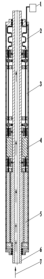
[0013] The present invention will be further described in detail in conjunction with the accompanying drawings. As shown in the figure, the rotating shaft of the permanent magnet synchronous motor 5 of the present invention is a hollow shaft 6, and the shell of the permanent magnet synchronous motor 5 and the hollow shaft 6 extend upwards. Between the shell and the hollow shaft 6 From bottom to top, there are permanent magnet synchronous motor 5, downhole controller 4, and protector 3; ground control cabinet 1 transmits power and control signals to permanent magnet synchronous motor 5 through downhole controller 4 through the electronic screen, and controls permanent magnet synchronous The motor 5 works; the upper and lower ends of the hollow shaft 6 are sealed and rotated with the casing. The cable barrel 2 arranged between the shell of the permanent magnet synchronous motor 5 and the hollow shaft 6 is located above the protector 3 . Bearings are installed between the permanent


PUM


Abstract

The invention discloses a permanent magnet synchronous motor device directly driving a drill bit. A rotating shaft of a permanent magnet synchronous motor is a hollow shaft, an outer shell and the hollow shaft of the permanent magnet synchronous motor extend upwards, the permanent magnet synchronous motor and a downhole controller are sequentially arranged between the outer shell and the hollow shaft from bottom to top, a cable is connected with the permanent magnet synchronous motor through the downhole controller, and the upper end and the lower end of the hollow shaft are in sealing rotation connection with the outer shell. A protector arranged between the outer shell and the hollow shaft is arranged on the downhole controller, and the protector is a precipitation type or capsule type protector. Motor oil is arranged in the protector, the cable is connected with a motor control cabinet, and the motor control cabinet transmits a power source and control signals to the permanent magnet synchronous motor via the downhole controller through the cable. A stator slot of the permanent magnet synchronous motor is a straight slot. Due to the fact that the output end of the permanent magnet synchronous motor can be directly connected with the drill bit, the drill bit is directly driven to work below thousands of meters, and the phenomena of breaking, falling and the like of a drill column can be effectively avoided.

Description


Claims


Application Information

Patent Timeline
Owner XINXIANG XIAFENG ELECTRIC LTC
Why Eureka
Try Eureka