Pressure plate and side plate respectively loaded to two high-pressure areas of double-acting vane pump

A pressure plate and vane pump technology, applied in the field of hydraulic components, can solve the problems of waste, loading, and the inability to separate the pressure plate and the side plate, and achieve the effects of reducing energy loss, saving installation space, and reliable performance.

Pending Publication Date: 2020-06-16
FUXIN DARE AUTOMOTIVE PARTS
View PDF0 Cites 0 Cited by
  • Summary
  • Abstract
  • Description
  • Claims
  • Application Information

AI Technical Summary

Problems solved by technology

As a quantitative pump, the speed of the oil pump is proportional to the speed of the engine, so the output flow of the oil pump is proportional to the speed of the engine. Obviously, when the speed of the engine is too high, the output of the oil pump must be greater than the

Method used


Image

  • Pressure plate and side plate respectively loaded to two high-pressure areas of double-acting vane pump
  • Pressure plate and side plate respectively loaded to two high-pressure areas of double-acting vane pump
  • Pressure plate and side plate respectively loaded to two high-pressure areas of double-acting vane pump

Examples


Embodiment Construction

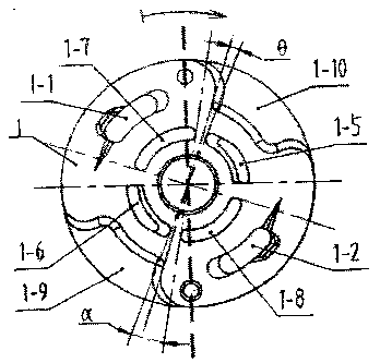
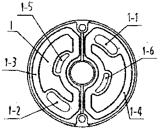
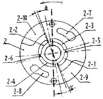
[0012] Examples, see attached Figure 1-3 The pressure plate and the side plate respectively loaded on the two high-pressure areas of the double-acting vane pump are symmetrically arranged at 180 degrees on the upper outer edge of the front of the pressure plate 1, and the oil outlet of the pressure plate 1-1 and the oil outlet of the pressure plate are provided. Two 1-2. The edge of pressure plate 1 between the head and tail of pressure plate oil outlet 1-1 and pressure plate oil outlet 2 1-2 is symmetrically provided with fan-shaped pressure plate oil suction window 1-9 and pressure plate oil suction window 2 1- 10. Out of the center hole of the pressure plate 1, there are circular pressure plate oil passage grooves 1-5, pressure plate oil passage grooves 2 1-8, pressure plate oil passage grooves 3 1-6 and pressure plate oil passage grooves 4 arranged symmetrically at 90 degrees outside the central hole of the pressure plate 1. 1-7. Pressure plate oil passage groove one 1-5


PUM


Abstract

The invention belongs to hydraulic components in mechanical industries, and particularly relates to a pressure plate and a side plate respectively loaded to two high-pressure areas of a double-actingvane pump. A pressure plate oil outlet I and a pressure plate oil outlet II are symmetrically formed at a 180-degree angle in the front of the pressure plate. A pressure plate oil suction window I anda pressure plate oil suction window II are symmetrically arranged at the edge of the pressure plate between heads and tails of the pressure plate oil outlet I and the pressure plate oil outlet II. The included angle between heads and tails of a pressure plate oil through groove I and a pressure plate oil through groove IV and a pressure plate oil through groove II and a pressure plate oil throughgroove III is alpha. The tangent line across the circle center at the beginning of the pressure plate oil through groove I and the connection line of the starting edge of the pressure plate oil suction window II and the circle center form a theta angle. The two oil outlets in the pressure plate in the pressure plate and the side plate loaded to the two high-pressure areas of the double-acting vane pump can be completely loaded independently so that the double-acting vane pump can realize two independent double pump functions.

Description


Claims


Application Information

Patent Timeline
Owner FUXIN DARE AUTOMOTIVE PARTS
Why Eureka
Try Eureka