Device for influencing passenger compartment noise

A noise and cabin technology, applied in active noise control, transportation and packaging, circuits or fluid pipelines, etc., can solve the problem that it is difficult for the driver to extract useful information

Active Publication Date: 2014-06-18
GM GLOBAL TECH OPERATIONS LLC
View PDF5 Cites 5 Cited by
  • Summary
  • Abstract
  • Description
  • Claims
  • Application Information

AI Technical Summary

Benefits of technology

This patented technology allows sensors located inside engines (such as those used with filters) to measure their temperatures accurately without being affected by outside factors like air flow around them.

Problems solved by technology

Technically speaking, there exist different ways to reduce annoying sounds inside vehicles like engine sound during cruising on city streets. However, these methods have limitations due to their ability to block out external sources such as background music or loudspeakers. Therefore, this technology has been developed specifically towards improving comfort levels within cabins where people tend to sleep too much.

Method used


Image

  • Device for influencing passenger compartment noise
  • Device for influencing passenger compartment noise

Examples


Embodiment Construction

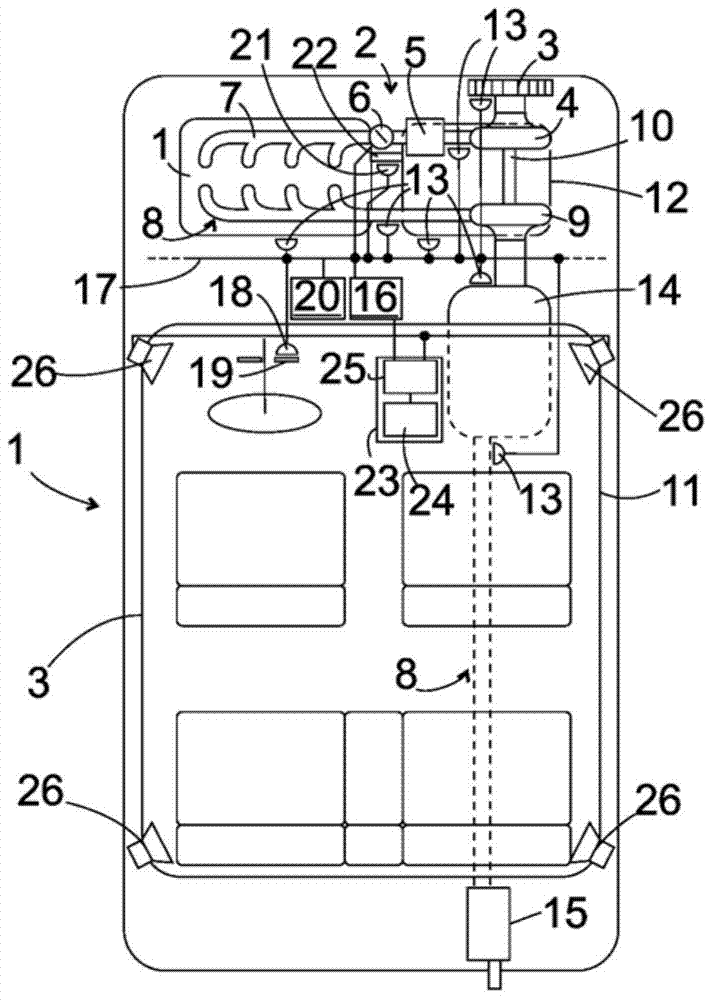
[0015] figure 1 A motor vehicle with a device for influencing cabin noise is shown schematically. The internal combustion engine of the vehicle, in particular a gasoline engine or a diesel engine, is designated with reference numeral 1 . On the intake line 2 of the engine 1 are arranged in sequence: an air filter 3, a compressor 4, a charge air cooler 5, a throttle valve 6 and an intake manifold 7 which distributes charge air to Inside the cylinder of engine 1.

[0016] A turbine 9 and an exhaust gas catalytic converter 14 or a particle filter are arranged on the exhaust gas line 8 of the engine 1 . The exhaust gas, which is depressurized in the turbine 9 , is driven in the compressor 4 via the shaft 10 in a known manner.

[0017] The driving noise that can be heard in the cabin 11 of the vehicle is jointly emitted by different noise sources, in particular the engine 1, the transmission 12 driven by the engine 1 and the drive chain arranged thereafter extending towards the dri


PUM


Abstract

A device is provided for influencing the passenger compartment noise in a motor vehicle includes, but is not limited to a noise signal generator for generating an offsetting noise signal, which includes, but is not limited to a control input for receiving a control signal that is representative of the engine load of the motor vehicle, and a loudspeaker for receiving the offsetting noise signal and emitting an offsetting noise into the passenger compartment of the motor vehicle. The noise signal generator furthermore includes, but is not limited to an input for a temperature signal of a temperature sensor and is equipped to generate the offsetting noise signal as a function of a signaled temperature.

Description


Claims


Application Information

Patent Timeline
Owner GM GLOBAL TECH OPERATIONS LLC
Why Eureka
Try Eureka