Double-fiber ball-shared coupling micro-measuring-force targeting sensor with end face micro-structure

A technology of aiming sensor and micro-measuring force, applied in measurement devices, instruments, optical devices, etc., can solve the problems of low primary magnification, low resolution, and reduced signal-to-noise ratio, so as to save costs and improve signal-to-noise ratio. The effect of improving the ratio and resolution

Inactive Publication Date: 2014-07-02
HARBIN INST OF TECH
View PDF3 Cites 18 Cited by
  • Summary
  • Abstract
  • Description
  • Claims
  • Application Information

AI Technical Summary

Benefits of technology

This new type of sensing device uses two fibers - one for light transmission and another for data reception – each having its own unique structure on their ends called a tip or feature point (FSP). These structures improve the quality of signals detected from these devices while also being able to measure smaller distances accurately due to high numerical aperture. Additionally, this design allows for flexibility when measuring larger areas within small holes through adjustment of both focusing and zoom levels during measurements. Overall, it provides better performance over existing technologies like LIDAR systems used today.

Problems solved by technology

Technologies for improving the measurement capabilities of opaque targets such as semiconductor devices include enlarged observation windows or multiplex measurements, but these techniques require expensive equipment and slow processing speeds. Additionally, they may cause delays in obtaining detailed results if applied close enough together.

Method used


Image

  • Double-fiber ball-shared coupling micro-measuring-force targeting sensor with end face micro-structure
  • Double-fiber ball-shared coupling micro-measuring-force targeting sensor with end face micro-structure
  • Double-fiber ball-shared coupling micro-measuring-force targeting sensor with end face micro-structure

Examples


Embodiment 1

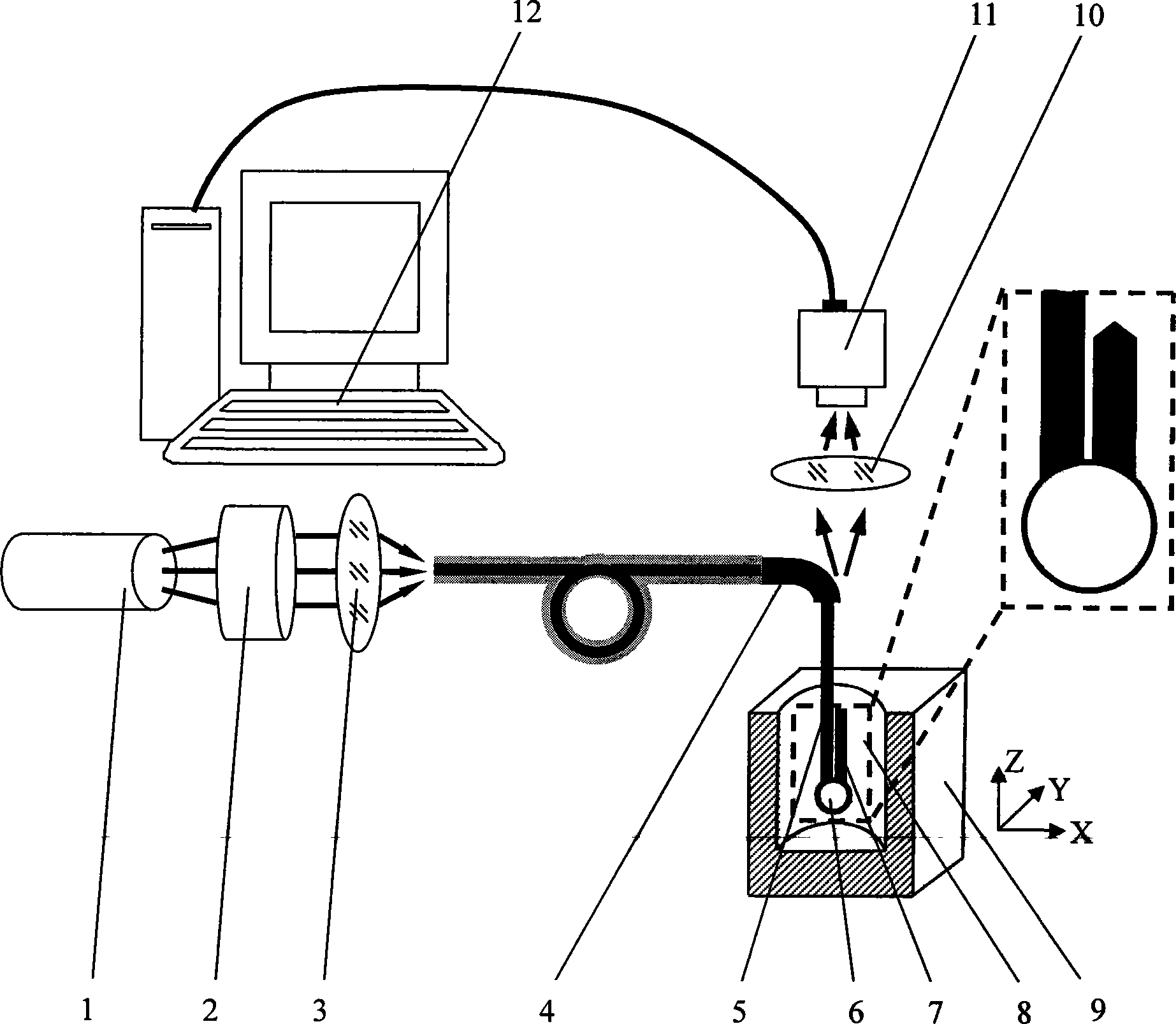
[0028] A dual-fiber co-spherical coupling micro-measurement force aiming sensor with an end-face microstructure, the sensor consists of a laser 1, a beam expander collimator 2, a fiber coupling lens 3, a catheter 4, a probe 8, a microscope objective 10, CCD camera 11 and computer 12 constitute, and data line is communicated with CCD camera 11 and computer 12, and probe 8 is placed in the microhole 9 to be measured; The outgoing fiber 7 with a microstructure, the coupler 6 is respectively connected to the incident fiber 5 and the exiting fiber 7 with a tapered end surface microstructure, the coupler 6 is used as the contact point of the probe 8, and the beam emitted by the laser 1 is collimated by expanding the beam The mirror 2 and the fiber coupling lens 3 enter the incident fiber 5, the light beam is introduced into the coupler 6 through the incident fiber 5, and then is exported by the outgoing optical fiber 7 with a tapered end microstructure, and the exported light beam enter

Embodiment 2

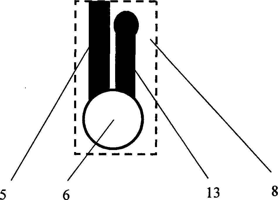
[0033] The probe 8 is composed of an incident optical fiber 5, a coupler 6 and an outgoing optical fiber 13 with an aspherical end surface microstructure, and the aspherical end surface microstructure improves the signal-to-noise ratio of the detection signal. Other parts and working process of this embodiment are all the same as Embodiment 1.

Embodiment 3

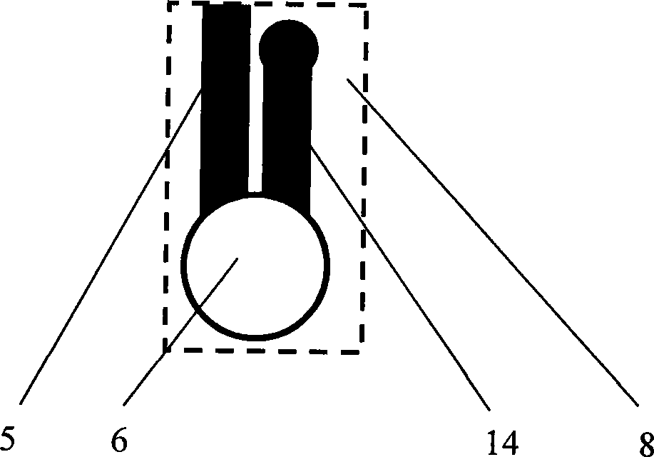
[0035] The probe 8 is composed of an incident optical fiber 5, a coupler 6 and an outgoing optical fiber 14 with a spherical end surface microstructure, and the spherical end surface microstructure improves the signal-to-noise ratio of the detection signal. Other parts and working process of this embodiment are all the same as Embodiment 1.


PUM


Abstract

The invention provides a double-fiber ball-shared coupling micro-measuring-force targeting sensor with an end face micro-structure, and belongs to the technology of precision instrument manufacture and measurement. The sensor comprises a laser device, a beam expanding collimating mirror, a fiber coupling lens, a guide pipe, a microscope objective, a CCD camera, a computer and a probe composed of an incidence fiber, a coupler and an outgoing fiber with the conical end face micro-structure. The coupler serves as a contact of the probe, and light beams are led out through the outgoing fiber with the conical end face micro-structure after being led into the coupler through the incidence optical fiber. The light beams which are led out enter the CCD camera through the microscope objective. The light spot energy center positions formed by the outgoing light beams on the CCD camera can be obtained through the image processing technology, and the targeting condition of the sensor in the space can be obtained through the one-to-one correspondence relation between the light spot energy center positions on the CCD camera and the spatial positions of sensor contacts. The outgoing fiber in the probe of the sensor is provided with the end face micro-structure, the signal to noise ratio of a detection signal is greatly increased, and the measurement resolving power of the sensor is improved.

Description


Claims


Application Information

Patent Timeline
Owner HARBIN INST OF TECH
Why Eureka
Try Eureka