Push pin machining method and assembly machine used in cooperation with same

A processing method, the technology of H-shaped nails, which is applied in metal processing, metal processing equipment, manufacturing tools, etc., can solve the problems of slow speed and high cost of H-shaped nails, and achieve the effects of fast production speed, labor saving and cost saving

Inactive Publication Date: 2014-08-20
徐敏
View PDF5 Cites 2 Cited by
  • Summary
  • Abstract
  • Description
  • Claims
  • Application Information

AI Technical Summary

Problems solved by technology

[0003] At present, the production method of I-shaped nails is generally to install several metal nails into the clamping mold through the screening conveyor and fix them, and then manually put the clamping mold into the injection molding machine to injec

Method used


Image

  • Push pin machining method and assembly machine used in cooperation with same
  • Push pin machining method and assembly machine used in cooperation with same
  • Push pin machining method and assembly machine used in cooperation with same

Examples


Embodiment Construction

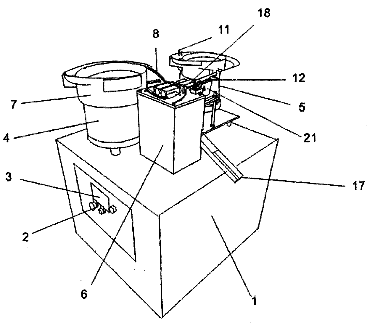
[0030] A method for processing H-shaped nails. First, an I-shaped cap with a large cap at one end and a small cap at the other end is produced in an injection molding machine, and a central hole is opened in the center of the large cap, and the central hole extends upward to the small cap. At the cap, a metal nail with a pointed end and a flat end is made on the forging equipment, and finally the I-shaped cap and the metal nail are assembled by a matching I-shaped nail assembly machine.

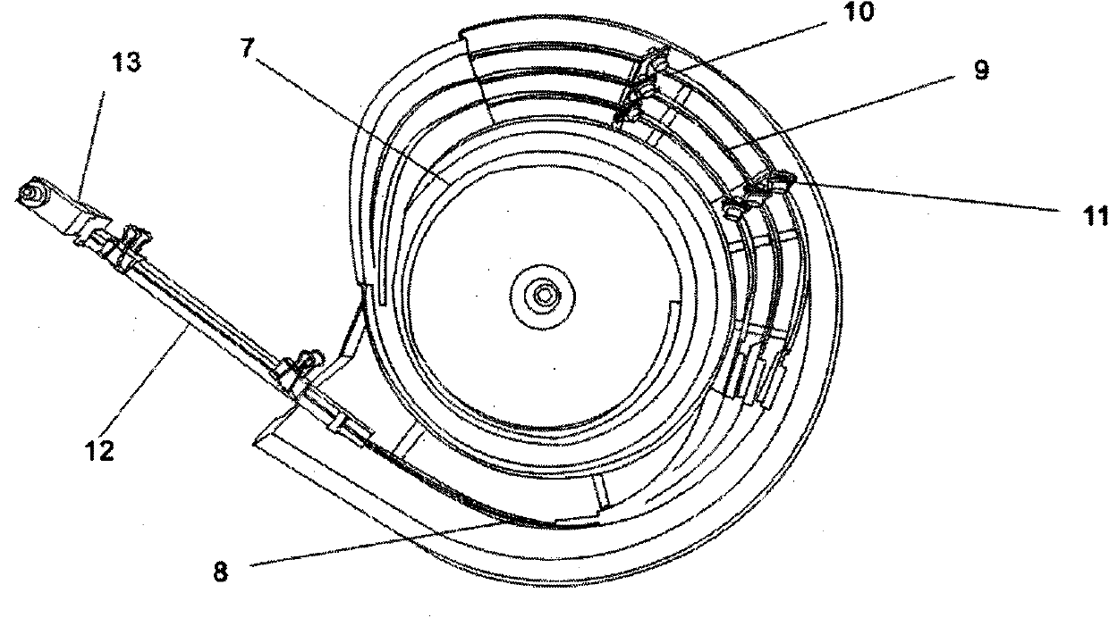
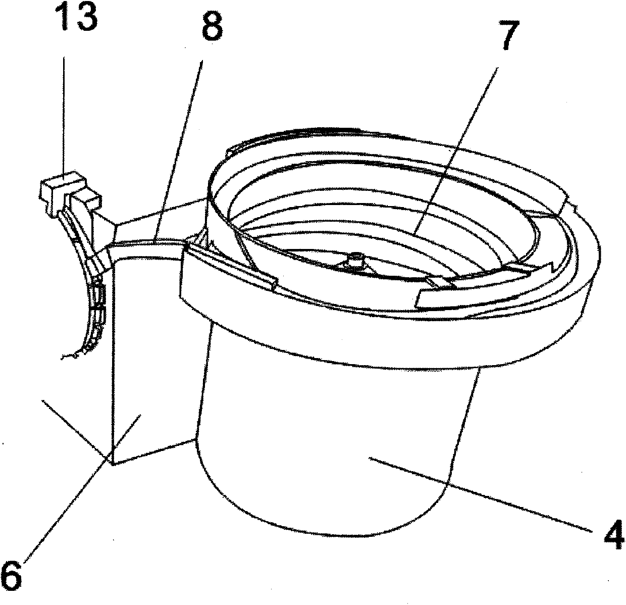
[0031] like Figure 1 to Figure 6 As shown, the H-shaped nail assembly machine used in conjunction with the processing method includes the H-shaped nail assembly machine body 1, and the control box located therein, the button 2 and panel 3 on the control box protrude from the body, and the H-shaped nails The top of the assembly machine body 1 is provided with an I-shaped cap conveyor 4, a metal nail conveyor 5 and a working box 6;

[0032] Both the I-shaped cap conveyor 4 and the metal nail con


PUM


Abstract

The invention discloses a push pin machining method and an assembly machine used in cooperation with the push pin machining method. The push pin machining method comprises the steps that firstly, a push pin cap is manufactured in an injection molding machine, wherein one end of the push pin cap is provided with a big cap, the other end of the push pin cap is provided with a small cap, and the center of the big cap is provided with a central hole which extends upwards to the small cap; secondly, a metal nail is manufactured on forging and pressing equipment, wherein one end of the metal nail is sharp, and the other end of the metal pin is flat; finally, the push pin cap and the metal pin are assembled through the push pin assembly machine used in cooperation with the method. The push pin machining method and the assembly machine have the advantages that continuous work can be achieved, and manufacturing speed is high; besides, a dozen of machines only need one person for monitoring, so that labor is greatly saved, and cost is greatly reduced.

Description


Claims


Application Information

Patent Timeline
Owner 徐敏
Why Eureka
Try Eureka