Wavefront subaperture inversion method of optical system

An optical system and sub-aperture technology, applied in measurement optics, optical devices, optical radiation measurement, etc., can solve the problems of difficulty and high cost in the development of large-diameter flat mirrors

Active Publication Date: 2014-10-08
BEIJING RES INST OF SPATIAL MECHANICAL & ELECTRICAL TECH
View PDF5 Cites 7 Cited by
  • Summary
  • Abstract
  • Description
  • Claims
  • Application Information

AI Technical Summary

Problems solved by technology

[0006] The technical problem of the present invention is: to overcome the deficiencies of the prior art, to provide a sub-aperture inversion method for the wavefront of the optical system, to use a small number of di

Method used


Image

  • Wavefront subaperture inversion method of optical system
  • Wavefront subaperture inversion method of optical system
  • Wavefront subaperture inversion method of optical system

Examples


Embodiment Construction

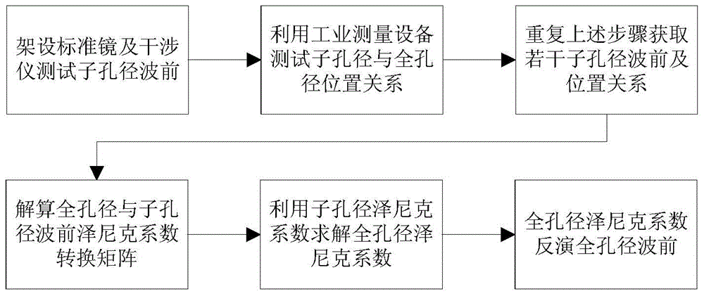
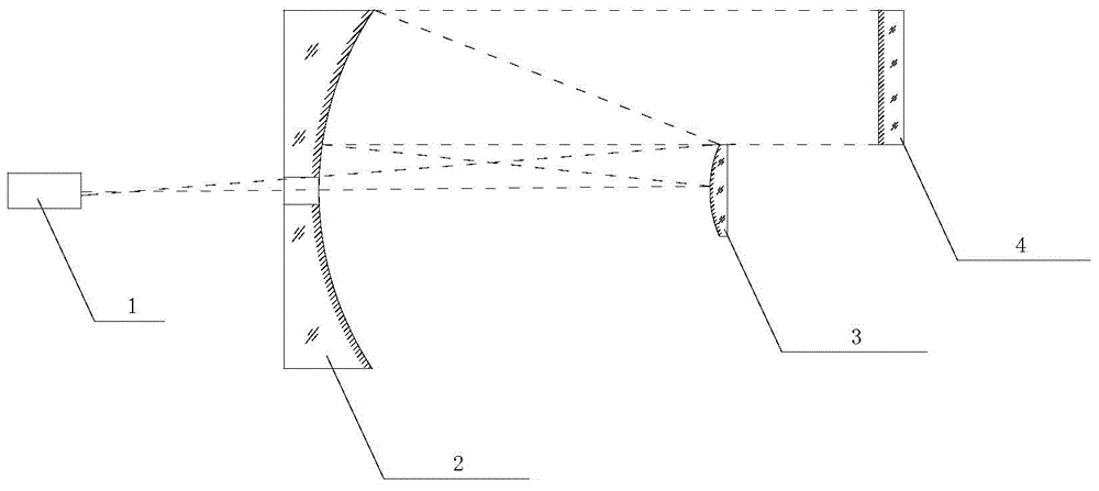
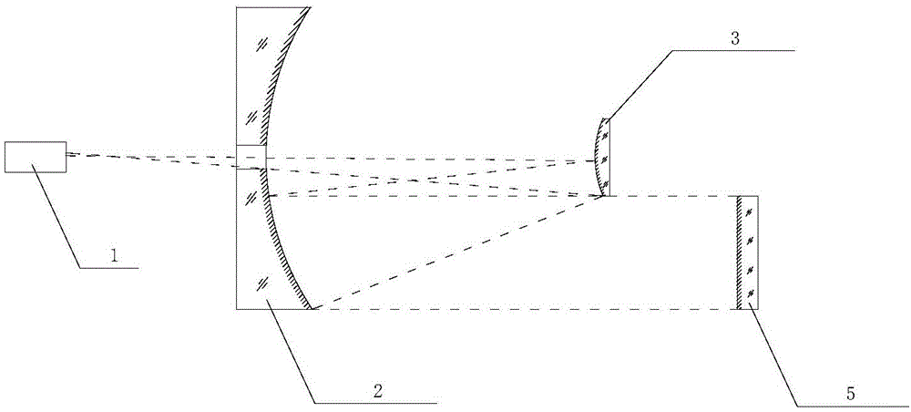
[0045] The flow process of the inventive method is as figure 1 As shown, the test configuration is as figure 2 , 3 As shown, the subaperture distribution is as Figure 4 shown. The invention utilizes the corresponding relationship between the full-aperture wavefront and the sub-aperture wavefront of the optical system, and solves the full-aperture wavefront through a small number of sub-aperture wavefront tests. The specific method flow is as follows:

[0046] 1) The interferometer 1 is placed at the focal plane position of the optical system, and the first sub-aperture plane mirror 4 is used to self-collimate to form an interference optical path; the optical system is an RC telescopic system composed of a primary mirror 2 and a secondary mirror 3;

[0047] 2) Use the interferometer 1 to obtain the wavefront error of the optical system corresponding to the first sub-aperture plane mirror 4, and use a laser tracker, an articulated measuring arm or other industrial measuring e


PUM


Abstract

The invention provides a wavefront subaperture inversion method of an optical system. The method comprises the steps that a plurality of subaperture wavefronts are tested, and the spatial location relation of a subaperture and a full aperture is acquired; the corresponding relation of the Zernike coefficients of the full aperture and all the subaperture wavefronts is solved, and a conversion matrix of the Zernike coefficients of the subaperture and the full aperture is established; the Zernike coefficients of the subaperture wavepoints are extracted, and the Zernike coefficient of the full aperture is solved through a matrix division method; the Zernike coefficient of the full aperture is inverted to obtain an accurate system wavefront. According to the wavefront subaperture inversion method of the optical system, the full aperture testing problem is solved by subaperture equipment, the test cost can be greatly saved, the number of needed subapeatures is small, and the testing efficiency is high.

Description


Claims


Application Information

Patent Timeline
Owner BEIJING RES INST OF SPATIAL MECHANICAL & ELECTRICAL TECH
Why Eureka
Try Eureka