Pneumatic tool motor with built-in beating mechanism

A technology of pneumatic tools and motors, applied in the field of partial structure of pneumatic tools, can solve the problems of heavy feeling, laborious use, and inconformity with industrial economic benefits, etc.

Inactive Publication Date: 2014-12-03
陈秀如 +1
View PDF7 Cites 1 Cited by
  • Summary
  • Abstract
  • Description
  • Claims
  • Application Information

AI Technical Summary

Problems solved by technology

[0004] The conventional setting structure of the striking mechanism is usually to add a front end reversing cover with a considerable axial length at the front end of the air motor of the air tool, so as to be assembled through the front end reversing cover The hammering seat, block hammer, rotary support shaft and other components of the striking mechanism are accommodated; however, because the striking mechanism is protruding from the front end of the air motor, the body of the pneumatic tool is relatively greatly increased. The axial length increases the lengt

Method used


Image

  • Pneumatic tool motor with built-in beating mechanism
  • Pneumatic tool motor with built-in beating mechanism
  • Pneumatic tool motor with built-in beating mechanism

Examples


Embodiment Construction

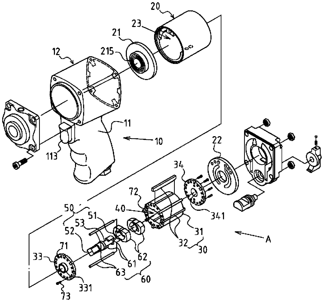
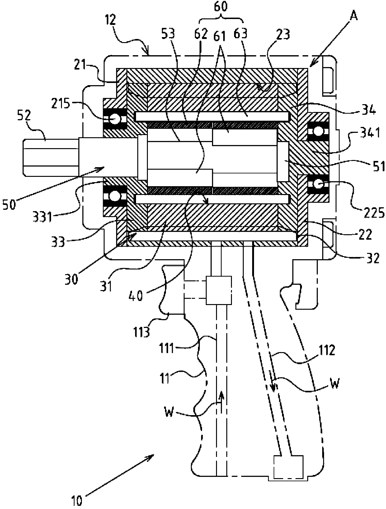
[0023] see figure 1 , 2 , 3, 4, the air tool motor A with a built-in striking mechanism of the present invention is located inside the body 12 formed by one end of the handle 11 (the top end in this embodiment) of an air tool 10, the handle 11 is detailed as image 3 As shown, it mainly includes an air intake channel 111, an exhaust channel 112 and a switch 113 to control the opening and closing of the air intake channel 111; the air tool motor A then includes the following components:

[0024] A cylinder block 20 is in the form of a hollow shell. The cylinder block 20 includes a front end wall 21, a rear end wall 22 and a cylinder chamber 23 that is cylindrical inside. The front end wall 21 is provided with a front end bearing 215, The rear end wall 22 is provided with a rear end bearing 225;

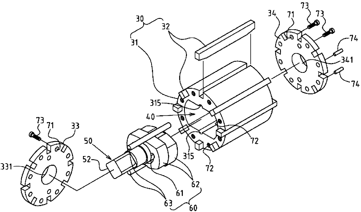
[0025] A rotor set 30 is rotatably accommodated in the cylinder chamber 23 of the cylinder block 20. The rotor set 30 includes a rotating drum 31 and at least two telescopic vanes 32 wi


PUM


Abstract

The invention discloses a pneumatic tool motor with a built-in beating mechanism. The pneumatic tool motor comprises an air cylinder body, a rotor group and an output shaft rod, wherein the rotor group comprises a drum and a telescopic blade, and the output shaft rod can be driven by the drum; an inner containing chamber is formed in the inner part of the drum of the rotor group; the output shaft rod is provided with a beating action zone which is positioned in the inner containing chamber; the inner containing chamber is internally provided with the built-in beating mechanism, and the built-in beating mechanism comprises a beating convex block which is arranged in the beating action zone in a bulged way, a movable beating hammer which is arranged at the periphery of the beating convex block in a sleeving way and a supporting post which is axially located on the drum. According to the pneumatic tool motor with the built-in beating mechanism, disclosed by the invention, the axial length and the volume of the pneumatic tool motor can be substantially reduced, and the advantage and advancement that the use is more labor-saving and more convenient can be achieved; the built-in beating mechanism of the pneumatic tool motor has the advantages that the rotor group can be directly driven, a twisting force can be increased immediately, and the disassembling and the locking of components are quick and convenient, and thus the pneumatic tool motor has the advantages that the multi-aspect cost can be substantially reduced, and the better industrial economic benefit can be obtained.

Description


Claims


Application Information

Patent Timeline
Owner 陈秀如
Why Eureka
Try Eureka