Lamp assembly structure

A technology for assembling structure and lamp body, which is applied to lighting devices, lighting device parts, light sources, etc., can solve the problems of inconvenient assembly, disassembly and automated production, and complex LED lighting ceiling spotlight processes, and achieves easy disassembly. And the effect of automatic production, simple structure and convenient assembly

Inactive Publication Date: 2014-12-03
LEEDARSON IOT TECH INC
View PDF7 Cites 0 Cited by
  • Summary
  • Abstract
  • Description
  • Claims
  • Application Information

AI Technical Summary

Problems solved by technology

However, although this method avoids the pulling of the wires and the light source board, it requires multiple screw locking actions, whi

Method used


Image

  • Lamp assembly structure
  • Lamp assembly structure
  • Lamp assembly structure

Examples


Embodiment Construction

[0015] The present invention will be further described in detail below in conjunction with the accompanying drawings and specific embodiments.

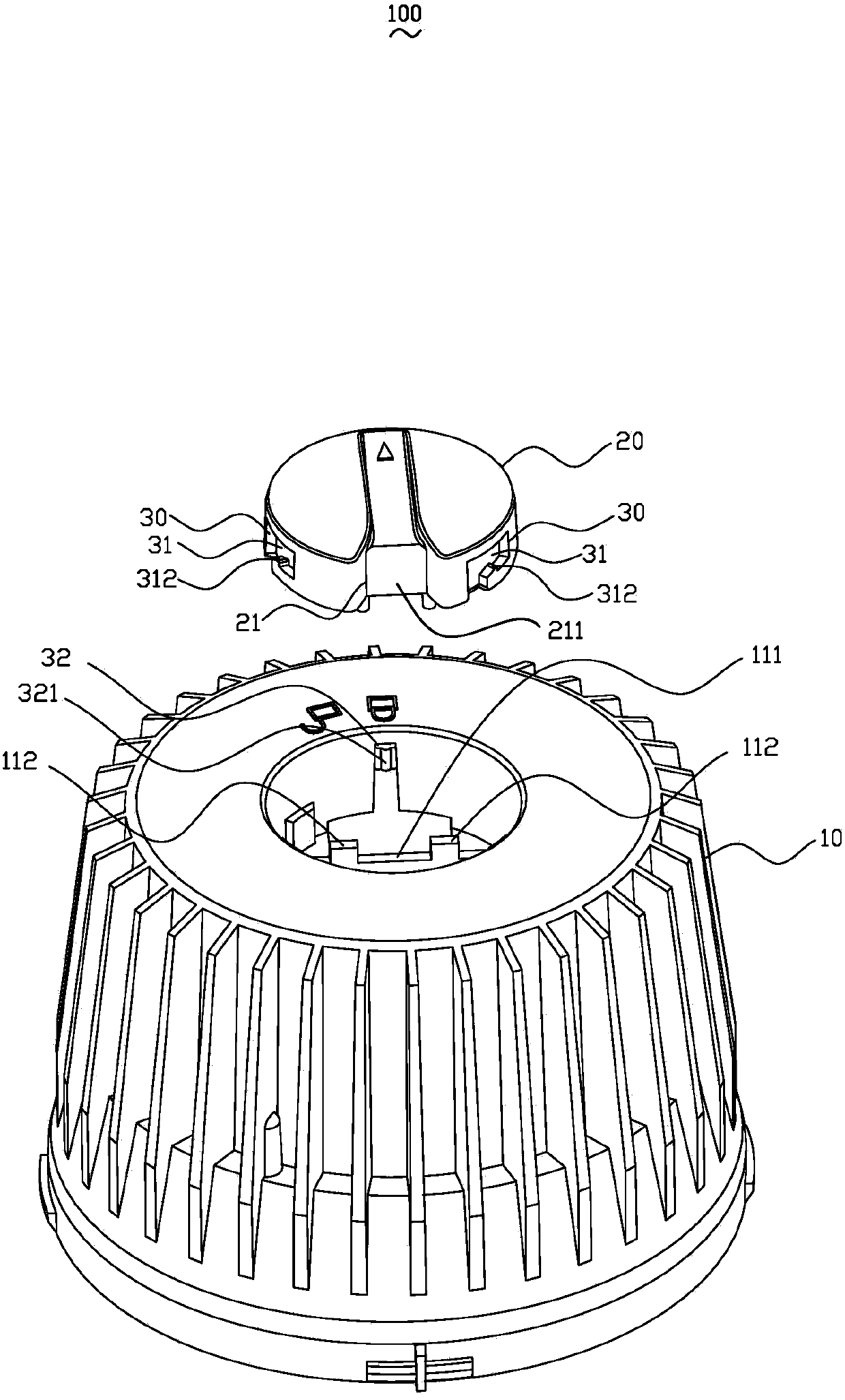
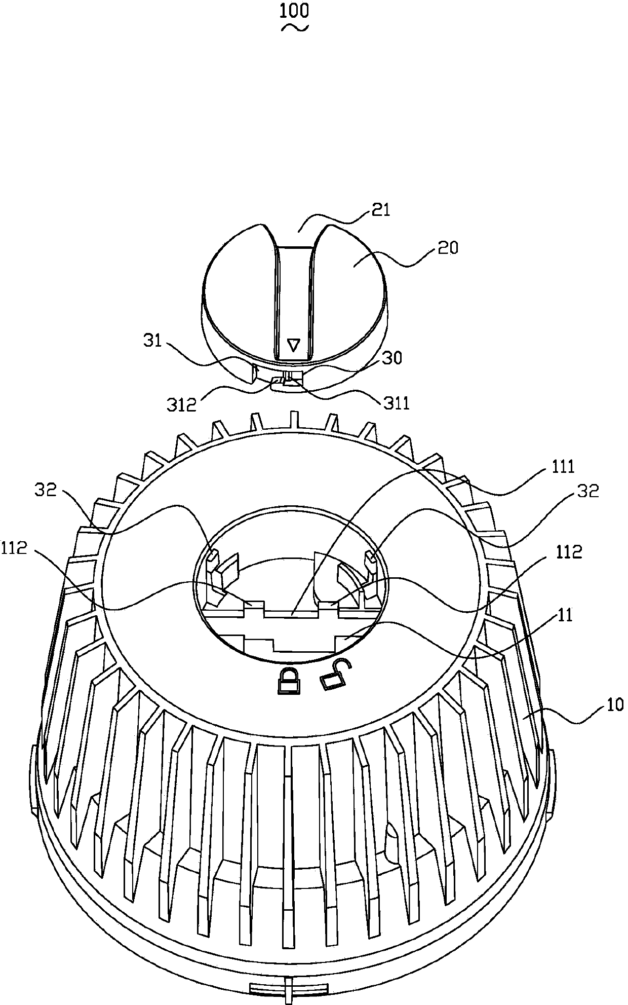
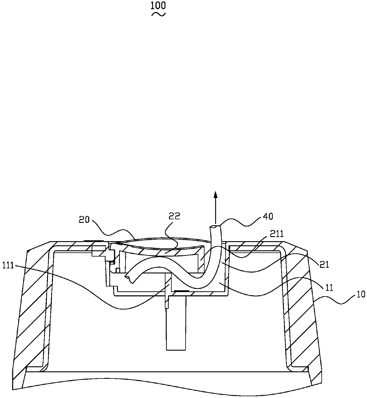
[0016] Please refer to Figure 1 to Figure 3 , the lamp body assembly structure 100 includes a lamp body 10, an upper cover 20, a turnbuckle structure 30 and an electric wire 40, the lamp body 10 is provided with a receiving groove 11 for accommodating the upper cover 20, and the upper cover 20 passes through the turnbuckle The structure 30 is buckled in the receiving groove 11 , the upper cover 20 is provided with a through hole 21 , and the wire 40 passes through the through hole 21 and extends out of the lamp head body 10 .

[0017] Please refer to Figure 1 to Figure 3 , the top of the lamp holder body 10 is provided with a receiving groove 11 . The bottom surface of the receiving groove 11 is provided with a limit bar 111, and the limit bar 111 deviates from the through hole 21 of the upper cover 20 in the vertical direction (such


PUM


Abstract

A lamp assembly structure comprises a lamp holder and a power cord. The lamp assembly structure is characterized by further comprising an upper cover and turn fastener structures. The lamp holder is provided with an accommodating recess used for accommodating the upper cover; the upper cover is fastened within the accommodating recess through the turn fastener structures; the upper cover is provided with a through hole which deviates from the center of the upper cover; the power cord penetrates the through hole and extends out of the lamp holder; the upper cover can be turned to unlock from the accommodating recess by turning the power cord. With the upper cover and the turn fastener structures, the lamp assemble structure needs no screws for locking the power cord; the lamp assembly structure has the advantages of convenience in assembly, simple structure, convenience is disassembly and production automation.

Description


Claims


Application Information

Patent Timeline
Owner LEEDARSON IOT TECH INC
Why Eureka
Try Eureka