Plug-pull-type fast lock for gauge board box cover

A plug-in, machine box technology, which is applied in the direction of building fastening devices, buildings, building structures, etc., can solve the problems of short service life, weakened elasticity, easy deformation, etc., and achieve long service life and stable clamping Effect

Inactive Publication Date: 2014-12-24
CHONGQING CHUANWU INSTR
View PDF0 Cites 2 Cited by
  • Summary
  • Abstract
  • Description
  • Claims
  • Application Information

AI Technical Summary

Problems solved by technology

The defect of the above structure is that the bolt is only clamped by the elastic force of the two halves of the leaf spring. After a period of

Method used


Image

  • Plug-pull-type fast lock for gauge board box cover
  • Plug-pull-type fast lock for gauge board box cover
  • Plug-pull-type fast lock for gauge board box cover

Examples


Embodiment 1

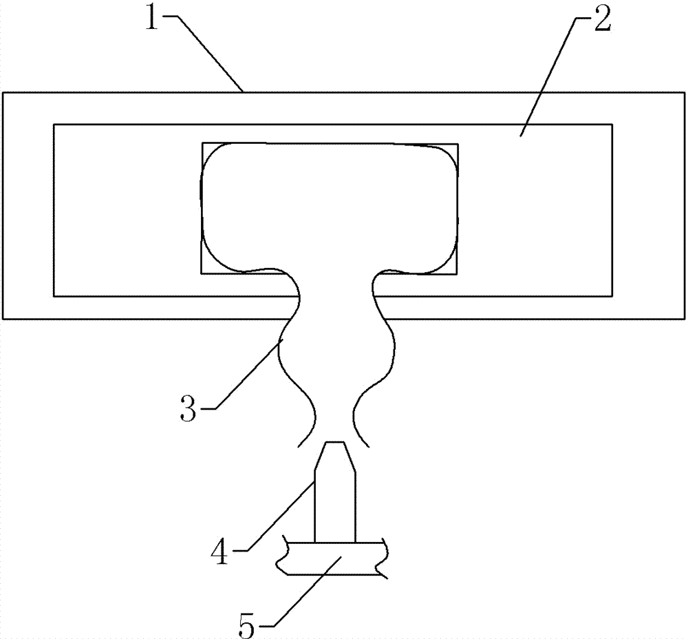
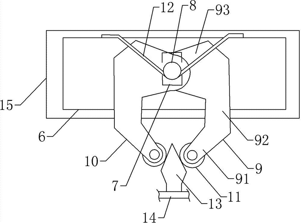
[0016] like figure 2 The shown plug-in quick lock for the instrument box cover includes a lock table 6, a slide hole 7, a support shaft 8, a first jaw 9, a second jaw 10, a guide roller 11, a torsion spring 12 and The dead bolt 13 and the lock platform 6 are arranged inside the instrument case 15 , and the dead bolt 13 is arranged on the inner side of the box cover 14 .

[0017] Both the first jaw 9 and the second jaw 10 include a connecting portion 93, a transition portion 92 and a clamping portion 91, the connecting portion 93, the transition portion 92 and the clamping portion 91 are in a “U” shape, and the first jaw 9 and The "U"-shaped openings of the second jaws 10 are opposite to each other. The lock table 6 is provided with a vertical slide hole 7, and the support shaft 8 is arranged in the slide hole 7 and has a vertical degree of freedom. The slide hole 7 plays a guiding role for the support shaft 8. Both the connecting parts 93 of the first jaw 9 and the second jaw

Embodiment 2

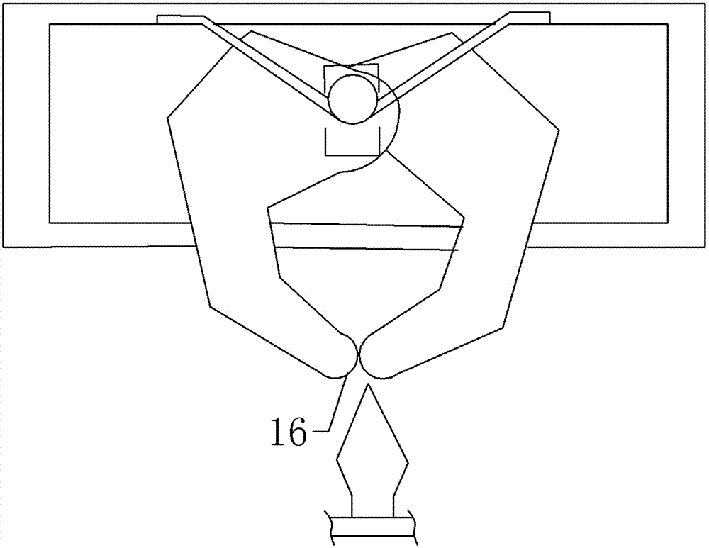
[0022] like image 3 As shown, when the lock tongue is not inserted into the clamping part, the clamping part of the first clamping jaw and the second clamping jaw are in contact. The only difference between this embodiment and the first embodiment is that the first clamping jaw and the second clamping jaw The outer ends of the clamping parts of the two jaws are all cylindrical curved surfaces 16 . The structural design of the cylindrical curved surface also guides the bolt.


PUM


Abstract

The invention provides a plug-pull-type fast lock for a gauge board box cover. The fast lock is long in service life and enough in clamping force. The fast lock comprises a spring bolt fixed on the inner side of the box cover and further comprises a lock table, a support shaft, a first claw, a second claw and a torsion spring which are arranged in a box body. A vertical slide hole is formed in the lock table, and the support shaft is arranged in the slide hole and has vertical degree of freedom. The first claw and the second claw both comprises a connection portion, a transition portion and a clamping portion, the connection portion, the transition portion and the clamping portion for a U shape, the U-shaped openings of the first claw and the second claw face each other, the connection portions of the first claw and the second claw are both hinged to the support shaft, the clamping portions of the first claw and the second claw abut against each other when not clamping the spring bolt, the middle of the torsion spring is wound around the support shaft to be located on one side of the clamping portion of each claw, two ends of the torsion spring are fixed on the lateral direction of the lock table, a tip is arranged at the front end of the spring bolt, and the rear end of the spring bolt is provided with the frustum-shaped clamping connection portion.

Description


Claims


Application Information

Patent Timeline
Owner CHONGQING CHUANWU INSTR
Why Eureka
Try Eureka