Bearing oiling auxiliary device

A technology of auxiliary devices and bearings, applied in the directions of bearing components, shafts and bearings, engine components, etc., can solve problems such as low efficiency, and achieve the effect of reducing workload, convenient operation, and reducing manual operation steps.

Active Publication Date: 2020-05-19
CIXI SIHAI BEARING
View PDF7 Cites 1 Cited by
  • Summary
  • Abstract
  • Description
  • Claims
  • Application Information

AI Technical Summary

Problems solved by technology

[0004] The technical problem to be solved by the present invention is to provide a bearing oili

Method used


Image

  • Bearing oiling auxiliary device
  • Bearing oiling auxiliary device
  • Bearing oiling auxiliary device

Examples


Embodiment Construction

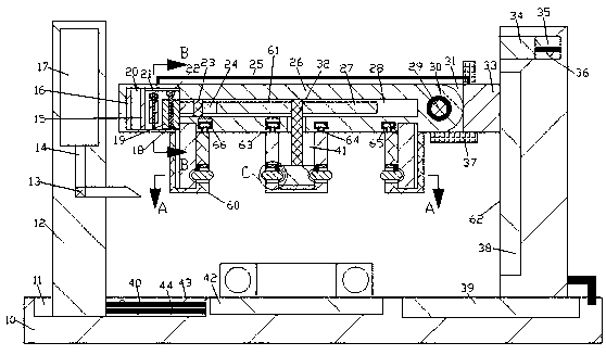
[0016] Combine below Figure 1-4 The present invention is described in detail, wherein, for the convenience of description, the orientations mentioned below are defined as follows: figure 1 The up, down, left, right, front and back directions of the projection relationship itself are the same.

[0017] combined with Figure 1-4 The described auxiliary device for oiling bearings includes a base 10, the upper end of the base 10 is provided with a conveyor belt 42 for conveying bearings, and the base 10 is also provided with an auxiliary mechanism 62 for assisting oiling, the conveyor belt 42, a support block 33 is provided on the upper side, and the support block 33 is provided with a rotating groove 31 with an opening to the left and an upper and lower end wall connected to the outside. A rotating shaft 29 is rotationally connected between the front and rear end walls of the rotating groove 31. The rod 59 is fixedly connected with the rear end wall of the rotating groove 31 by a


PUM


Abstract

The invention discloses a bearing oiling auxiliary device which comprises a base, wherein a conveyor belt for conveying a bearing is arranged on the upper end face of the base; an auxiliary mechanismfor assisting oiling is further arranged on the base; a support block is arranged on the upper side of the conveyor belt; a rotary groove is formed in the support block, the opening of the rotary groove is leftwards, and the upper end wall and the lower end wall of the rotary groove communicate with the external part; a rotary shaft is rotatably connected between the front end wall and the rear end wall of the rotary groove; a sliding rod is fixedly connected with the rear end wall of the rotary groove through a torsion spring; and a rotary plate is further fixedly connected onto the rotary shaft, and the left end of the rotary plate is positioned at the external part. The bearing oiling auxiliary device is simple in structure and convenient and fast in operation, automatically finishes the process of taking, placing and oiling through mechanical driving to reduce the step of manual operation, improve the working efficiency and lower the workload, and automatically finishes rotation ofinner and outer rings after oiling to uniformly apply lubricating oil between the inner and outer rings and improve the oiling quality.

Description


Claims


Application Information

Patent Timeline
Owner CIXI SIHAI BEARING
Why Eureka
Try Eureka