Electronic equipment and charging and discharging control method

A technology for electronic equipment and controllers, which is applied in the charging/discharging of secondary batteries, battery circuit devices, current collectors, etc., and can solve the problems of wireless charging methods with large limitations and no use of wireless charging.

Inactive Publication Date: 2015-04-15
LENOVO (BEIJING) CO LTD
View PDF4 Cites 5 Cited by
  • Summary
  • Abstract
  • Description
  • Claims
  • Application Information

AI Technical Summary

Benefits of technology

This patented solution allows for better utilization of electricity by providing two devices: one being able to charge another battery while it's still running; this second device also receives its own power when there are no more needs.

Problems solved by technology

The technical problem addressed by this patented method for wirelessly charged electronic products lies in how users may charge their own batteries more efficiently while also having access to other battery types like mobile phones due to limited space available on both these two items.

Method used


Image

  • Electronic equipment and charging and discharging control method
  • Electronic equipment and charging and discharging control method
  • Electronic equipment and charging and discharging control method

Examples


Embodiment Construction

[0068] The following will clearly and completely describe the technical solutions in the embodiments of the present invention with reference to the accompanying drawings in the embodiments of the present invention. Obviously, the described embodiments are only some, not all, embodiments of the present invention. Based on the embodiments of the present invention, all other embodiments obtained by persons of ordinary skill in the art without making creative efforts belong to the protection scope of the present invention.

[0069] Embodiment 1 of the present invention discloses an electronic device, which may be a mobile phone, a tablet computer, a palmtop computer, a power bank, and the like.

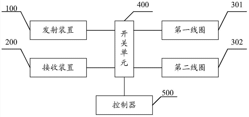
[0070] Such as figure 1 As shown, the electronic device may include: a transmitting device 100, a receiving device 200, a first coil 301, a second coil 302, a switch unit 400, and a controller 500; wherein:

[0071] The transmitting device 100 is connected to the first coil 301 through the


PUM


Abstract

The invention discloses electronic equipment and a charging and discharging control method. The electronic equipment comprises an on-off unit, a transmitting device, a first coil connected with the transmitting device through the on-off unit, a receiving device, a second coil connected with the receiving device through the on-off unit, and a controller connected with the on-off unit, wherein the controller is used for controlling the on-off unit according to the current state of the electronic equipment to enable the transmitting device or the receiving device to be started; as the transmitting device can supply power to other electric equipment, the receiving device can receive the electric energy of other power supply equipment. Therefore, the electronic equipment disclosed by the invention can be used as both the power supply equipment and the electronic equipment, and further, a wireless charging technology is greatly popularized.

Description


Claims


Application Information

Patent Timeline
Owner LENOVO (BEIJING) CO LTD
Why Eureka
Try Eureka