Distributed gas sensing system and control method thereof
A gas sensing and control method technology, applied in the direction of color/spectral characteristic measurement, etc., can solve the problems of difficult networking, inability to meet regional multi-point measurement, high cost of single-point measurement, and achieve the effect of reducing system cost
- Summary
- Abstract
- Description
- Claims
- Application Information
AI Technical Summary
Problems solved by technology
Method used
Image

Examples
Embodiment 1
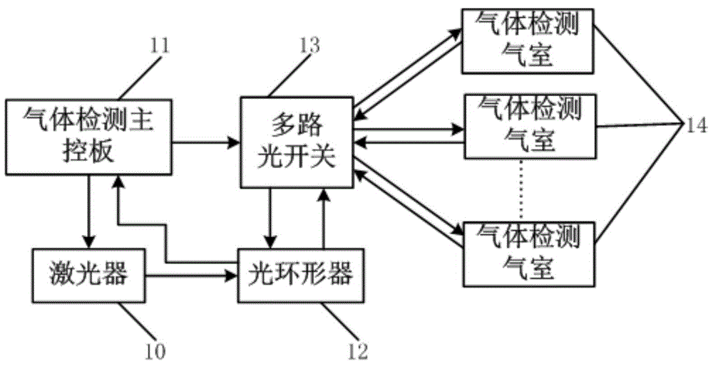
[0046] figure 1 A schematic structural diagram of the distributed gas sensing system provided by Embodiment 1 of the present invention is given, as figure 1 As shown, the distributed gas sensing system includes: a laser 10, a gas detection main control board 11, an optical circulator 12, a multi-channel optical switch 13 and at least one gas detection gas chamber 14;
[0047] Among them, the gas detection main control board 11 is used to drive the laser 10 and control the gating of the multi-channel optical switch 13;
[0048] The first port of the optical circulator 12 is connected to the output end of the laser 10, the second port is connected to the multi-channel optical switch 13, and the third port is connected to the gas detection main control board 11, which is used to transmit the laser signal output by the laser 10 to the multi-channel optical switch 13. switch 13, and transmit the laser signal fed back from the multi-channel optical switch 13 to the gas detection main
Embodiment 2
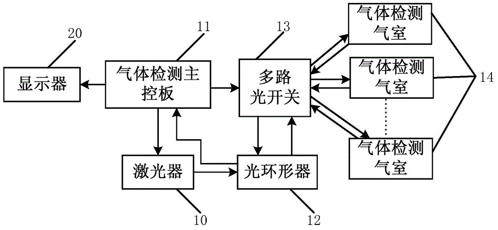
[0055] figure 2 A schematic structural diagram of the distributed gas sensing system provided by Embodiment 2 of the present invention is given, as figure 2 As shown, the difference from Embodiment 1 of the present invention is that the system also includes:
[0056] The display 20 is used to display the gas concentration calculation result, and the display 20 is connected with the gas detection main control board 11 through a serial communication interface.
[0057] Wherein, the display 20 can be connected with the gas detection main control board 11 through the RS-232 interface, and the gas detection main control board 11 calculates the gas concentration through a corresponding algorithm, and displays it to the user through the display 20 .
[0058] In this embodiment, the gas detection gas chamber 14 includes an outer tube and a total reflection mirror arranged inside the other end facing the input / output end. The total reflection mirror can reflect back all the laser lig
Embodiment 3
[0071] Figure 4 A flow chart of the control method of the distributed gas sensing system provided by Embodiment 3 of the present invention is given, as shown in Figure 4 As shown, the control method of the distributed gas sensing system includes the following steps:
[0072] S10. The gas detection main control board controls multiple optical switches to select one laser signal;
[0073] In this step, the controller of the gas detection main control board can send a control signal instruction to the multi-channel optical switch through the RS232 interface to realize the switching of the multi-channel optical switch. ×16 channels, 1×32 channels can also be selected.
[0074] S11. The gas detection main control board drives the laser light source to scan the laser modulation wavelength;
[0075] In this step, the gas detection main control board can output a DA control signal to the laser through the RS232 interface to drive the laser to output laser of corresponding wavelength
PUM
 Abstract
Description
Claims
Application Information
 - R&D Engineer
- R&D Manager
- IP Professional
- Industry Leading Data Capabilities
- Powerful AI technology
- Patent DNA Extraction
Browse by: Latest US Patents, China's latest patents, Technical Efficacy Thesaurus, Application Domain, Technology Topic.
© 2024 PatSnap. All rights reserved.Legal|Privacy policy|Modern Slavery Act Transparency Statement|Sitemap