Jib structure, jib system and crane

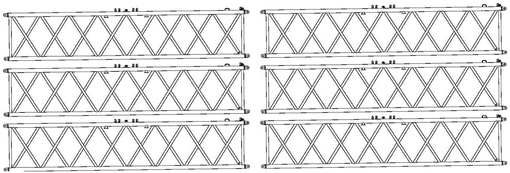
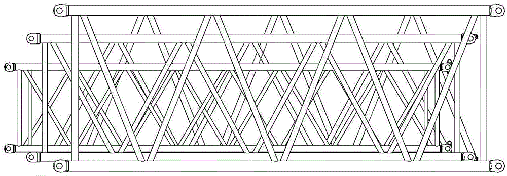
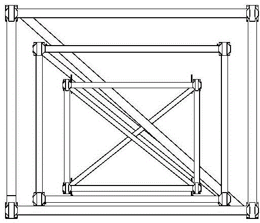
A crane and boom technology, applied in the field of construction machinery, can solve problems such as limited internal space, boom prone to collision, friction, collision and friction, etc., and achieve the effect of reducing vehicles transporting boom structures

Inactive Publication Date: 2015-05-06
XCMG CONSTR MACHINERY
View PDF5 Cites 1 Cited by
  • Summary
  • Abstract
  • Description
  • Claims
  • Application Information

AI Technical Summary

Problems solved by technology

Depend on image 3 From the top view of the boom structure, it can be seen that the upper and lower surfaces of the boom structure are arranged with different numbers of horizontal and vertical crossbars. During the nesting and assembly process of the boom, when the Figure 4 In the position shown, due to the interference of the crossbar on the upper surface of the boom, the nesting process cannot continue. At this time, only the Figure 4 Remove the hanging point, select another lifting point or use other auxiliary means for nesting assembly, the nesting assembly efficiency is low, and during the replacement of the hanging point or the embedding pro

Method used


Image

  • Jib structure, jib system and crane
  • Jib structure, jib system and crane
  • Jib structure, jib system and crane

Examples


Embodiment Construction

[0056]The technical solutions in the embodiments of the present invention will be clearly and completely described below in conjunction with the drawings in the embodiments of the present invention. Apparently, the described embodiments are only some of the embodiments of the present invention, not all of them. Based on the embodiments of the present invention, all other embodiments obtained by persons of ordinary skill in the art without creative efforts fall within the protection scope of the present invention.

[0057] In describing the present invention, it is to be understood that the terms "central", "longitudinal", "transverse", "front", "rear", "left", "right", "vertical", "horizontal", The orientations or positional relationships indicated by "top", "bottom", "inner", "outer", etc. are based on the orientations or positional relationships shown in the drawings, and are only for the convenience of describing the present invention and simplifying the description, rather th


PUM


Abstract

The invention relates to a jib structure, a jib system and a crane. The jib structure comprises a jib body which comprises a plurality of side surfaces and two end surfaces, wherein all the side surfaces are welded by a plurality of cross bars, and a roller device is arranged on the cross bar in one side surface. According to the jib structure, the roller device is arranged on the jib body, the jib structure with the small cross section is nested into the jib structure with the large cross section by the roller device, the jib sections with the different cross sections can be nested and assembled, and the quantity of vehicles for transporting the jib structure can be reduced.

Description


Claims


Application Information

Patent Timeline
Owner XCMG CONSTR MACHINERY
Why Eureka
Try Eureka