Rooter

The technology of a soil tiller and a soil knife is applied in the field of soil tillers, which can solve the problems of low efficiency and high labor intensity, and achieve the effects of high labor efficiency and convenient operation.

Inactive Publication Date: 2015-05-20
LIUZHOU MEINA MACHINERY
View PDF7 Cites 5 Cited by
  • Summary
  • Abstract
  • Description
  • Claims
  • Application Information

AI Technical Summary

Problems solved by technology

[0003] The technical problem to be solved by the present invention is to provide a soil tille

Method used


Image

  • Rooter
  • Rooter

Examples


Embodiment Construction

[0011] The present invention will be described in further detail below in conjunction with accompanying drawing embodiment:

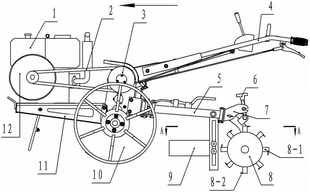
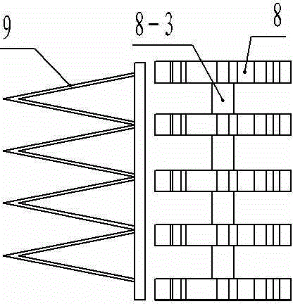
[0012] figure 1 , figure 2 The tiller shown, (the direction indicated by the arrow is the forward end of the tiller) includes a driving machine 1 arranged on a vehicle frame 11 and a clutch 3 controlled by operating the handle 4, and the driving machine 1 passes through the belt 2 is connected with the clutch 3, the clutch 3 is connected with the driving wheel 10 through the gearbox, and the rear end of the vehicle frame 11 is connected with the soil cutting knife 9 and the soil turning roller 8 sequentially through the connecting rod 5, and the connecting rod 5 and the Between the turning rollers 8, there is an adjusting piece 7 that adjusts the position of the turning rollers 8 through the knob 6. There are multiple soil cutting knives 9 and the turning rollers 8, and the soil cutting knives 9 are correspondingly arranged on two adjacent turning roller


PUM


Abstract

The invention discloses a rooter, and belongs to the technical field of farm machinery. The rooter comprises a driving machine and a clutch, wherein the driving machine is arranged on a frame; the clutch is controlled through an operation handle; the driving machine is connected with the clutch through a belt; the clutch is connected with a driving wheel through a speed changing box; the rear end of the frame is sequentially connected with a plurality of soil opening blades and a plurality of soil turning rollers from front to back; each soil opening blade is arranged at the front end of a portion between the two corresponding adjacent soil turning rollers; front ends of the soil opening blades are connected to one another; the soil opening blades are opened rearwards and are conical; each soil turning roller sleeves a corresponding roller shaft through a corresponding roller seat and extends in the radial direction to form a plurality of soil turning blades; and a plurality of soil breaking teeth are arranged on the top of each soil turning blade and is perpendicular to the soil turning blade. By the rooter, the problem that the soil turning labor intensity is high and the efficiency is low in the existing farming process can be solved.

Description


Claims


Application Information

Patent Timeline
Owner LIUZHOU MEINA MACHINERY
Why Eureka
Try Eureka