Roller way conveying buffer segment

A buffer section, roller table technology, applied in the direction of roller table, transportation and packaging, can solve the problems of sliding friction, bumping and scratching items, affecting the conveying volume and productivity, etc., to reduce sliding friction and improve service life.

Active Publication Date: 2009-05-27
NUCTECH CO LTD
View PDF0 Cites 6 Cited by
  • Summary
  • Abstract
  • Description
  • Claims
  • Application Information

AI Technical Summary

Problems solved by technology

In such a process, if it is not handled properly, when the speed changes from fast to slow, the following items will hit the front items, so that the transport of the items cannot be carried out smoothly, or bumps and scratches will occur between the items, thus affecting the appearance of the items (products). Quality; or the gap between the front and rear items is

Method used


Image

  • Roller way conveying buffer segment
  • Roller way conveying buffer segment

Examples


Embodiment Construction

[0014] The present invention will be described in detail below with reference to the accompanying drawings.

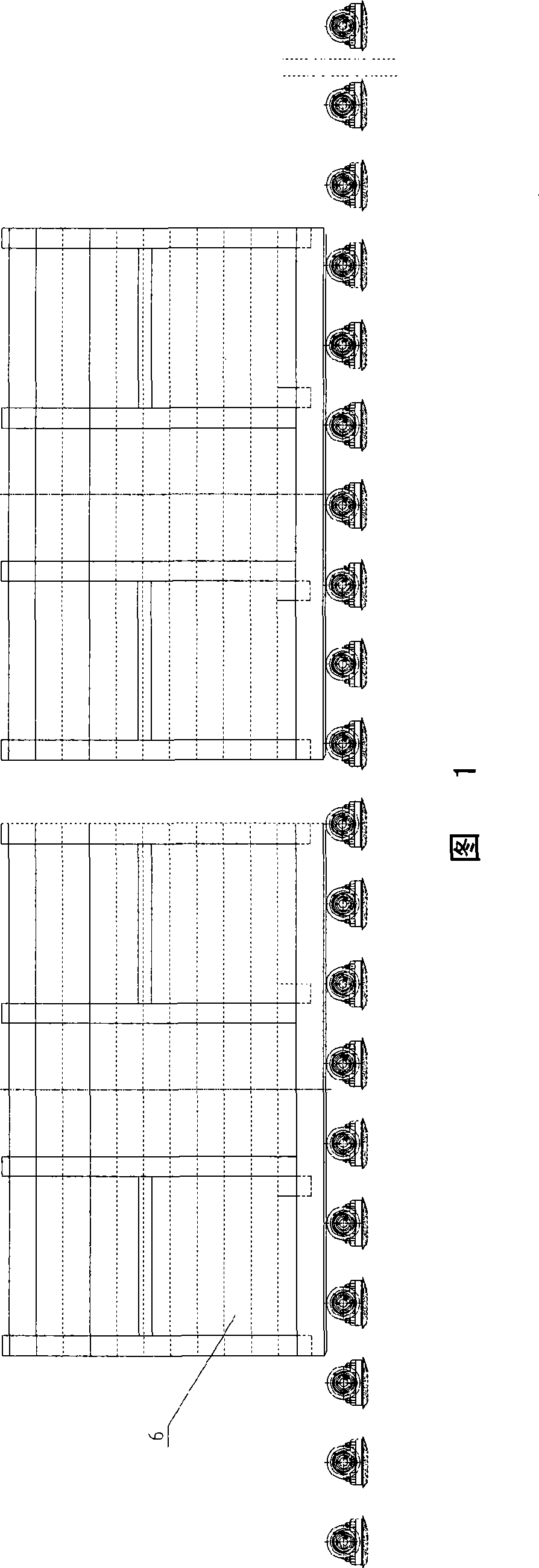
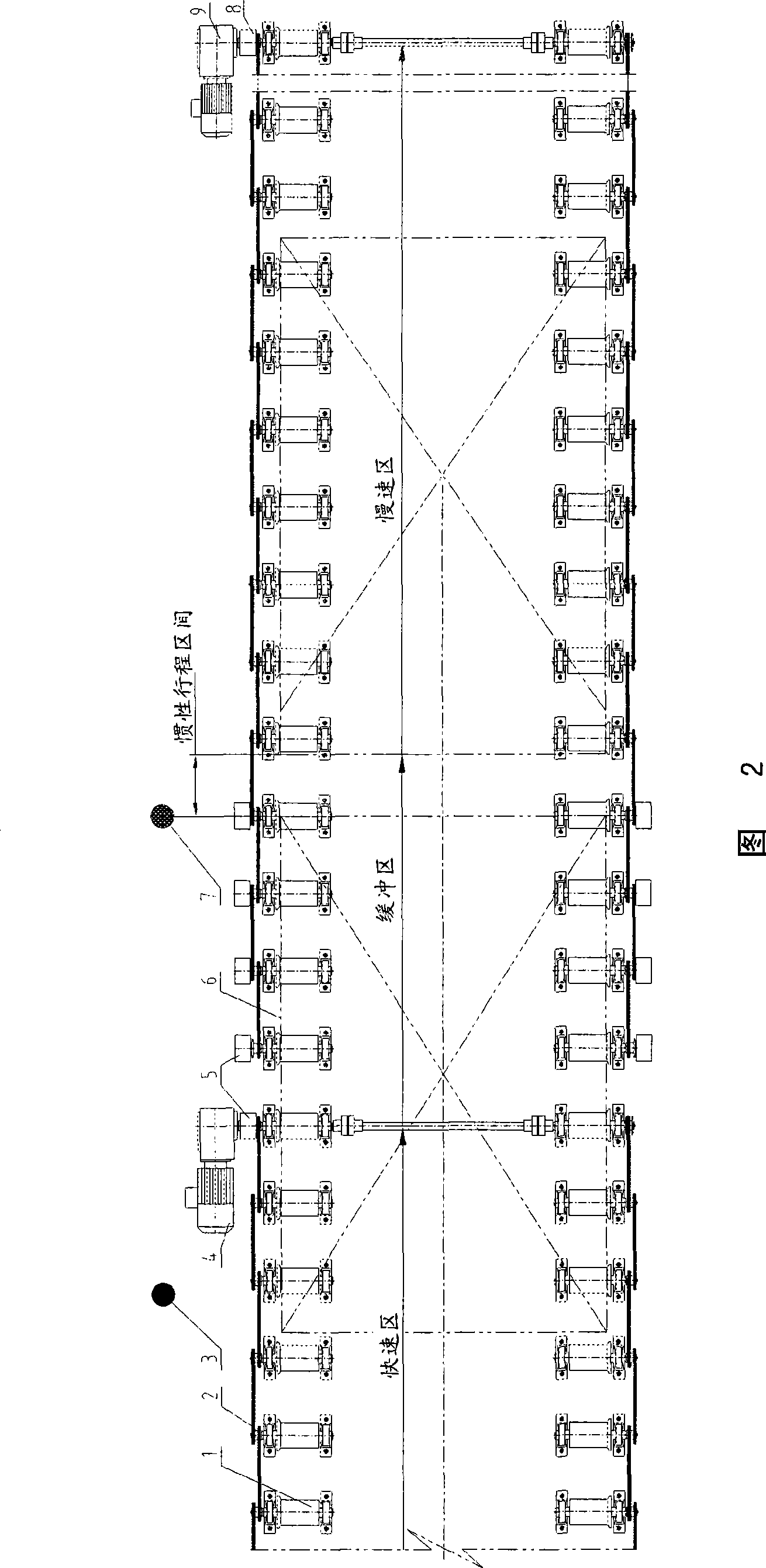
[0015] The buffer section of the present invention is divided into a fast zone, a buffer zone and a slow zone, mainly including: idler roller 1, sprocket, chain 2, position sensor 3 for controlling departure time, motor reducer 4 in fast zone, overrunning clutch 5 and 8 , the position sensor 7 that sends out the fast and slow speed conversion signal, and the motor reducer 9 in the slow speed zone. In the present invention, the position sensor can be a photoelectric sensor or other sensors.

[0016] The working principle of the present invention will be briefly described below, and the specific structures of components known in the prior art will not be described in detail here. The article 6 runs fast on the roller table, and still advances at a fast speed when entering the buffer zone from the fast zone. The motor reducer 9 in the slow zone does not need to change the s


PUM


Abstract

The invention provides a novel roller table conveying buffer segment for high-low speed switching, which aims at the process requirements on roller table conveying that an article at the back needs to catch up with another article in the front. The roller table conveying buffer segment comprises a fast speed zone, a buffer zone and a slow speed zone, wherein the fast speed zone is provided with a carrying roller and a fast speed zone motor reducer; the buffer zone is provided with a carrying roller, an overrunning clutch and a position transducer; and the slow speed is provided with a carrying roller and a slow speed zone motor reducer, wherein when the articles enter the buffer zone from the fast speed zone, the fast speed zone motor reducer slows down according to a signal from the position transducer in the buffer zone, and the carrying roller in the buffer zone is changed into a driven carrying roller by the overrunning clutch. When the novel roller table conveying buffer segment is used for continuous zero clearance (little clearance) conveying of various articles with high-low speed switching, the sliding friction between the articles and the contacting surfaces of the carrying rollers and the bumping among the articles are reduced, and the adjacent articles can be effectively contacted.

Description


Claims


Application Information

Patent Timeline
Owner NUCTECH CO LTD
Why Eureka
Try Eureka