Speed reducer

A technology of reducer and deceleration transmission, which is applied in the direction of door/window accessories, wing leaf parts, gear transmission devices, etc. It can solve the problems of unstable output torque, laborious trouble, and affecting the life of the transmission accuracy of the transmission pair, so as to reduce the applied force. The space occupied by the force and the axial direction is small, and the effect of meeting the transmission requirements of the large reduction ratio

Active Publication Date: 2012-06-27
CHERY AUTOMOBILE CO LTD
View PDF6 Cites 8 Cited by
  • Summary
  • Abstract
  • Description
  • Claims
  • Application Information

AI Technical Summary

Benefits of technology

This technology allows for better performance at high speeds when transmitting power through two different types of drive systems with reduced size compared to traditional methods like pulleys or belts. It also reduces the amount of effort required during maintenance tasks on vehicles that use these drives due to their smaller sizes.

Problems solved by technology

This technical problem addressed in this patented text relates to improving the stability or consistency of transmitting force from one part (usually called the input) into another part without causing instability during manual operation.

Method used


Image

  • Speed reducer
  • Speed reducer
  • Speed reducer

Examples


Embodiment Construction

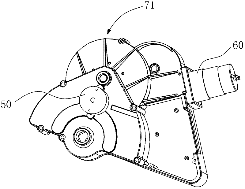
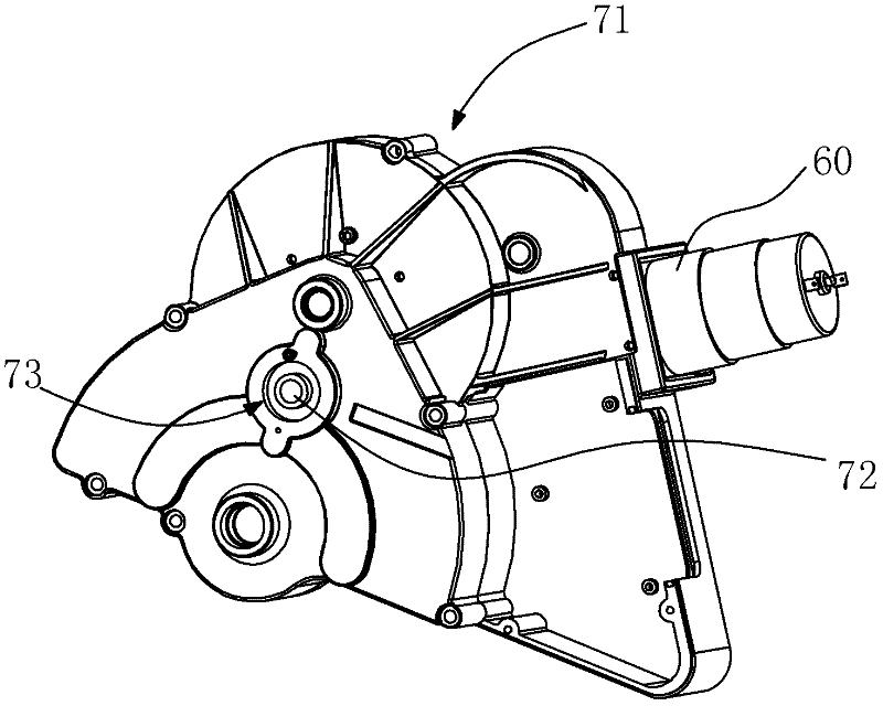
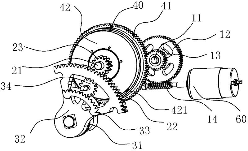
[0013] The present invention will be further described below in conjunction with the accompanying drawings.

[0014] Such as figure 1 , figure 2 , image 3 As shown, the speed reducer includes a housing 71, and the airtight cavity in the housing 71 is provided with a three-stage reduction transmission mechanism, and the reduction transmission mechanisms of each stage are gear meshing transmissions, which are connected with the output end of the motor 60 and serve as a The worm 14 of the first-stage main transmission meshes with the first-stage driven gear 12 to form the first-stage reduction transmission pair, and the second-stage driving gear 13, which is coaxially fixed with the first-stage driven gear 12, meshes with the second-stage driven gear teeth 22 to form the second stage. The three-stage driving gear 23 coaxially arranged with the two-stage driven gear 22 and the three-stage output gear 32 constitute the third-stage reduction transmission pair, and the three-stage d


PUM


Abstract

The invention relates to the field of mechanical transmission, in particular to a speed reducer of an opening mechanism of an automobile trunk door, which is used in the opening and closing mechanism of an automobile trunk door and is a three-stage gear meshing transmission mechanism. A clutch is arranged between a secondary driven gear and a triple driving gear. The adoption of the technical scheme has the advantages that the power transmission requirements on large speed reducing ratio can be met; the stability of the output torque is improved; and labor is saved when the automobile trunk door is manually opened.

Description


Claims


Application Information

Patent Timeline
Owner CHERY AUTOMOBILE CO LTD
Why Eureka
Try Eureka