Crane force feedback system
A technology of force feedback and cranes, which is applied in the direction of cranes, load hanging components, safety devices, etc., can solve the problems of poor operability of cranes, low lifting efficiency and safety, etc., to achieve poor operability, improve efficiency and safety effect
- Summary
- Abstract
- Description
- Claims
- Application Information
AI Technical Summary
Benefits of technology
Problems solved by technology
Method used
Image

Examples
Embodiment 1
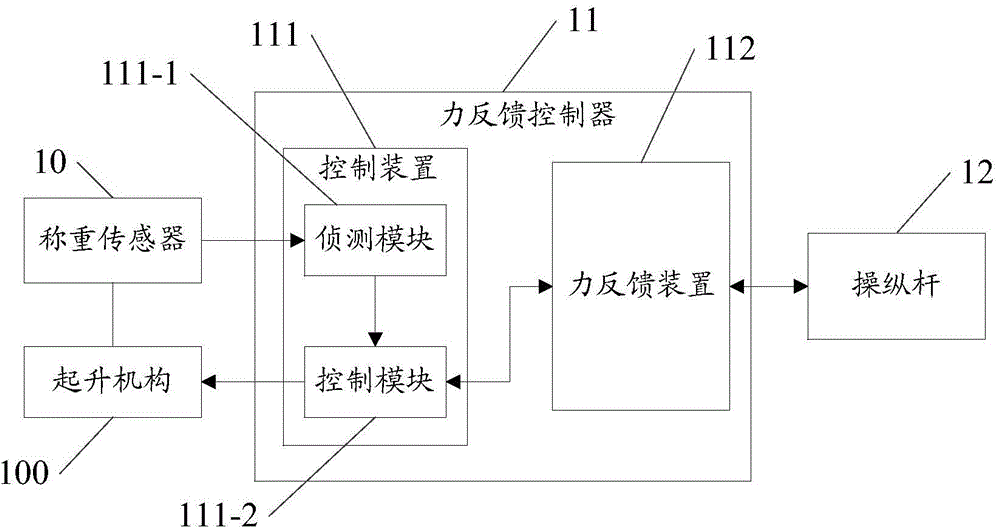
[0036] Please refer to figure 1, the embodiment of the present application provides a crane force feedback system, the system includes:
[0037] Load cell 10 is connected with the hoisting mechanism 100 of the crane;
[0038] A force feedback controller 11, connected to the load cell 10;
[0039] Joystick 12, connected with the force feedback controller 11;
[0040] Wherein, the load cell 10 is used to obtain the weight signal of the cargo to be moved by the lifting mechanism 100, and convert the weight signal into a first signal; the force feedback controller 11 is used to receive the first signal a signal, and convert the first signal into a feedback force that can be recognized by the operator of the crane based on a first conversion method, and drive the joystick 12 through the feedback force, so that the operator The weight of the cargo can be sensed while holding the joystick 12 .
[0041] In the specific implementation process, please continue to refer to figure 1 , t
Embodiment 2
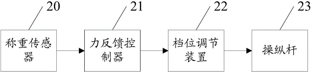
[0061] Please refer to figure 2 , in the specific implementation process, in order to apply force to the joystick according to the actual operation needs, so that the operator can feel the force of different sizes, the system also includes:
[0062] The gear adjustment device 22 connected to the force feedback controller 21 and the joystick 23 respectively is used to control the force feedback controller 21 to apply the feedback force to the joystick 23 .
[0063] That is to say, the force feedback controller 21 obtains the weight signal of the lifted goods through the load cell 20, and after converting it into the feedback force through the first conversion method, it needs to adjust the weight signal according to the current gear position of the joystick 23. The magnitude of the feedback force applied to the joystick 23 is determined. In practical application, the operator can choose different gears according to their own physical conditions. The high gear corresponds to a la
Embodiment 3
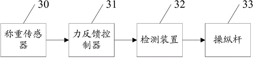
[0066] In order to be able to control the lifting mechanism of the crane to carry out the lifting operation based on the actions of the operator, the system further includes: a detection device connected to the joystick for detecting the manipulation effect exerted by the operator on the joystick force, and convert the manipulation force into a third signal and output it to the force feedback controller, so that the force feedback controller converts the third signal into a lifting force for lifting goods or applies The feedback force on the joystick is cleared.
[0067] That is, refer to image 3 , in the embodiment of the present application, the force feedback system includes: a load cell 30 , a force feedback controller 31 , a detection device 32 and a joystick 33 . The specific connection relationship of each component module is as follows: image 3 As shown, the working principle of each module is the same as that of the force feedback system in Embodiment 1, and will not
PUM
 Abstract
Description
Claims
Application Information
 - R&D Engineer
- R&D Manager
- IP Professional
- Industry Leading Data Capabilities
- Powerful AI technology
- Patent DNA Extraction
Browse by: Latest US Patents, China's latest patents, Technical Efficacy Thesaurus, Application Domain, Technology Topic.
© 2024 PatSnap. All rights reserved.Legal|Privacy policy|Modern Slavery Act Transparency Statement|Sitemap