Swing type sealing feeder

A feeder and feeding technology, which is applied in the field of feeders, can solve the problems of breakage of fragile materials, vibration feeders without sealing function, etc., and achieve the effect of adjustable feeding volume

Inactive Publication Date: 2015-05-27
焦作市润禾科技有限公司
View PDF5 Cites 0 Cited by
  • Summary
  • Abstract
  • Description
  • Claims
  • Application Information

AI Technical Summary

Benefits of technology

The invention describes an improved design for a swing gate that has better protection from damage caused during use or accidental impacts on it's components. This improves safety when used at high speeds while still being effective against external shock loads such as falling objects.

Problems solved by technology

The technical problem addressed in this patented text relates to improving the design for feeders used at food processing facilities by preventing damaging effects caused by brittle material being fed through them without having an effective seal mechanism or reducing any unwanted movements associated therewith.

Method used


Image

  • Swing type sealing feeder
  • Swing type sealing feeder

Examples


Embodiment Construction

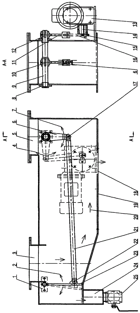
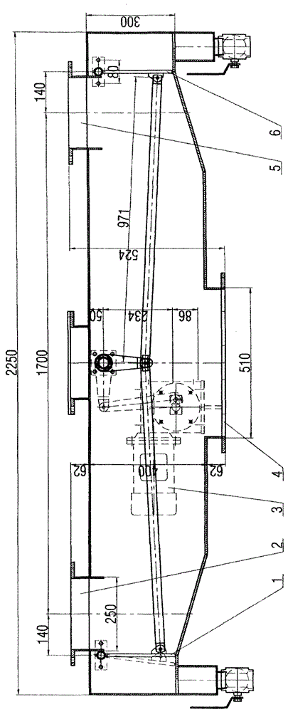
[0009] The geared motor 13 drives the crank 14 to rotate, the crank drives the connecting rod 16 outside the chamber to reciprocate up and down, the connecting rod 16 drives the rocker 11 outside the chamber to swing up and down along the arrow 4, and the rocker outside the chamber 11 drives the rocker inside the chamber through the rocker shaft 9 6 swings horizontally along the arrow 7, and the rocker 6 in the cavity drives the swing door 23 to swing horizontally along the arrow 2 through the connecting rod 21 in the cavity. The material enters the cavity from the material inlet 3, and is discharged from the cavity from the material outlet 18 along the arrow 20 under the swinging action of the swing door 23. During the whole process, the material and the outside air are effectively isolated by the casing 19; the material is squeezed and damaged to a small extent during the whole process. During the working process, a very small amount of material will enter the buffer bin 24, an


PUM


Abstract

The invention relates to a swing type sealing feeder. The swing type sealing feeder is suitable for quantitative continuous feeding which has a sealing requirement. The swing type sealing feeder comprises a swing door, a connecting bar in a cavity, a shell, a rocker shaft, a rocker in the cavity, a connecting bar outside the cavity, a rocker outside the cavity, a crank and a gear motor, the swing door is hinged to the shell through a sliding bearing pedestal, the swing door is hinged to the connecting bar in the cavity through a pin shaft, the connecting bar is hinged to the rocker in the cavity through a pin shaft, the rocker in the cavity, the rocker shaft and the rocker outside the cavity are firmly connected through keys, the connecting bar is hinged to the crank through a pin, and the crank is fixed on the output shaft of the gear motor. By means of said scheme, the swing type sealing feeder is capable of guaranteeing the sealing in the continuous feeding process and protecting fragile material from damage in a certain degree in the feeding process, and the yield is adjustable.

Description


Claims


Application Information

Patent Timeline
Owner 焦作市润禾科技有限公司
Why Eureka
Try Eureka