Online weighing roller way

A roller table and weighing technology, applied in the directions of weighing, measuring devices, instruments, etc., can solve the problems of high reconstruction cost and increase the civil foundation, and achieve the effect of low installation and reconstruction cost and easy installation.

Inactive Publication Date: 2015-12-23
BEIJING ZHONGYUANTONG SCI & TECH
View PDF7 Cites 5 Cited by
  • Summary
  • Abstract
  • Description
  • Claims
  • Application Information

AI Technical Summary

Benefits of technology

This technology uses a special mechanism that measures weight accurately while it moves along with the material being measured. Unlike traditional methods where materials have been removed from their place at manufacture time, this new method doesn't require any extra equipment like punchouts for added weights. Instead, these measurements take into account factors such as how well they work over varying temperatures and other environmental variables. Overall, this innovation makes it easier and less expensive than current methods.

Problems solved by technology

This technical problem addressed in this patents relates to improving the precision and efficiency when measuring weights during continuously castings processes used in manufacturers such as Iron & Steel Manufacture (IWM). Current methods require separate equipment and expensive materials, making them challenges to maintain their effectiveness due to factors including environmental conditions and thermal effects affects.

Method used


Image

  • Online weighing roller way
  • Online weighing roller way
  • Online weighing roller way

Examples


Embodiment 1

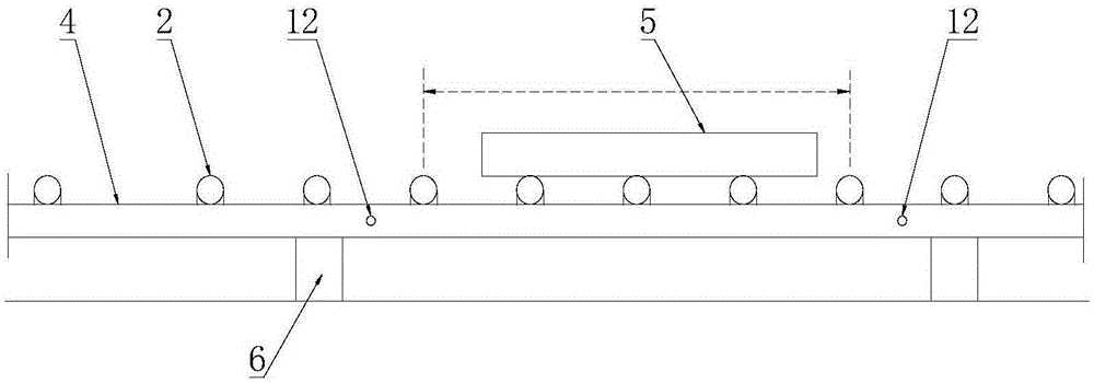
[0026] Such as figure 2 As shown, based on the above content, specifically, a pair of shear force sensors 12 are provided, and no support column 6 is provided in the measurement area. That is to say, the measurement area is set between two adjacent supporting columns 6, so that only a pair of shear force sensors 12 are needed to realize weighing detection.

[0027] Since the shear force sensor 12 is directly installed on the original conveying roller table 4, there is no need to cut off the conveying roller table 4, no need to modify the conveying roller table 4 during installation, no need to increase the civil foundation, no hydraulic system, and low weighing cost.

[0028] When weighing, after the workpiece 5 to be weighed is completely moved into the measuring area, the roller 2 stops rotating, the workpiece 5 no longer moves, and the shear force sensor 12 detects a parameter change, and the weight corresponding to the change is the weight of the workpiece 5. When the workp

Embodiment 2

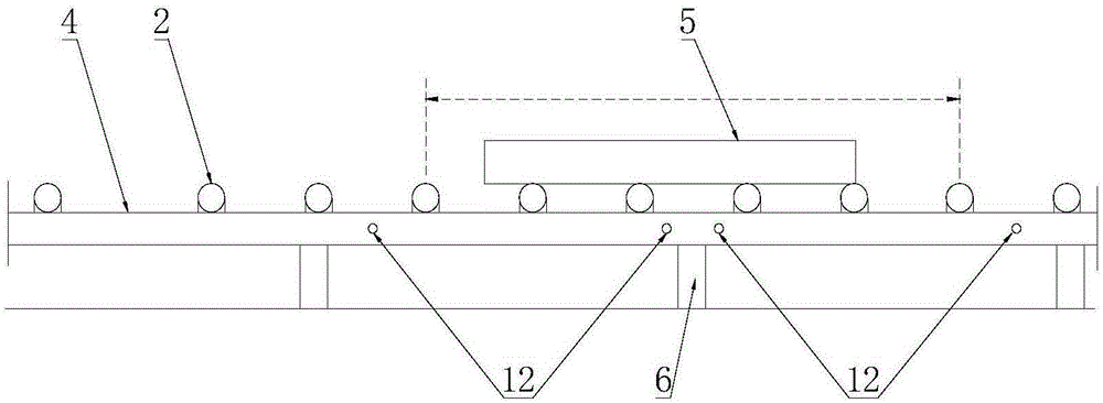
[0030] Such as image 3 As shown, this embodiment is basically the same as Embodiment 1, the difference is that there are support columns 6 for supporting the conveying roller table 4 in the measurement area, and at least one support column 6 is provided on both sides of each support column 6 For the shear force sensors 12 , at least one pair of shear force sensors 12 is provided between two adjacent support columns 6 .

[0031] image 3 Shown is a schematic diagram of only one support column 6 in the measurement area, so that the influence of the support column 6 on the weighing result can be eliminated, and the true value of the workpiece 5 weight can be obtained after comprehensive processing of the detection results of many pairs of shear sensors 12, and the measurement The result is not affected, and workpieces with longer lengths can be measured 5 .

Embodiment 3

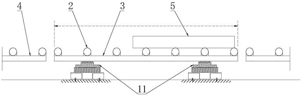
[0033] Such as Figure 4 As shown, this embodiment is basically the same as Embodiment 1, the difference is that a support column 6 is provided in the measurement area, and a pressure sensor 11 is connected to the support column 6 . Specifically, the pressure sensor 11 is arranged at the bottom of the support column 6 .


PUM


Abstract

The invention belongs to the technical field of online weighing in the metallurgy industry, and discloses an online weighing roller way. The online weighing roller way comprises a conveying roller way, wherein multiple rollers are uniformly arranged on the conveying roller way; one or more pairs of shear force sensors are mounted on the conveying roller way; multiple shear force sensors are formed to a measuring area; and workpieces to be weighed pass through the measuring area under a rotating effect of the roller way. A weighing structure provided with the shear force sensors on the conveying roller way is adopted to install under the preconditions of not cutting off the conveying roller way and not adding a civil foundation, so that the normal production is not influenced, and the improvement cost is low; one or more pairs of shear force sensors are only simply installed on the side surface of the conveying roller way to realize online weighing, so that the installation is simple and convenient; the conveying roller way has no need to be cut off, and can theoretically extend infinitely; and the measuring area can be arranged in any place on the conveying roller way as needed to satisfy the demands of different working conditions.

Description


Claims


Application Information

Patent Timeline
Owner BEIJING ZHONGYUANTONG SCI & TECH
Why Eureka
Try Eureka