Exhausting wave-resistant water stop device

A water-stopping device and anti-wave technology, which is applied in the direction of exhaust devices, noise reduction devices, engine components, etc., can solve problems such as economic loss, bombing, damage, etc., to reduce floating resistance, reduce resistance, and improve reliability Effect

Active Publication Date: 2016-02-17
710TH RES INST OF CHINA SHIPBUILDING IND CORP
View PDF6 Cites 5 Cited by
  • Summary
  • Abstract
  • Description
  • Claims
  • Application Information

AI Technical Summary

Problems solved by technology

[0003] The underwater vehicle is driven by a diesel engine. During normal operation, a part of the exhaust pipe is located underwater and a part is exposed to the water surface. Rainwater enters the exhaust pipe, and if it is submerged underwater, the seawater will directly pour into the exhaust pipe, causing the high-temperature diesel engine to blow up, damage, and the aircraft to sink, resulting in major safety accidents and economic losses
Conside

Method used


Image

  • Exhausting wave-resistant water stop device
  • Exhausting wave-resistant water stop device
  • Exhausting wave-resistant water stop device

Examples


Embodiment Construction

[0023] The present invention will be described in detail below with reference to the accompanying drawings and examples.

[0024] This embodiment provides an anti-wave and water-proof device used on an underwater vehicle. The device is connected to the exhaust pipe of the vehicle. Anti-surge, anti-rainwater and water-stop function when submerged in water for a moment, so as to ensure the safety of the aircraft.

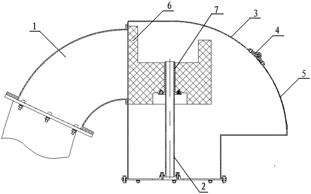
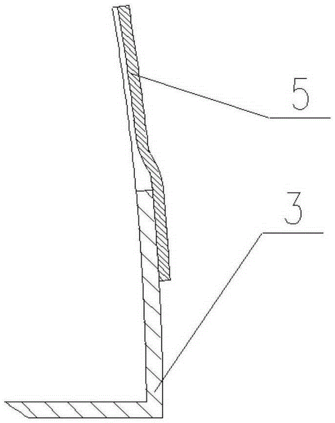
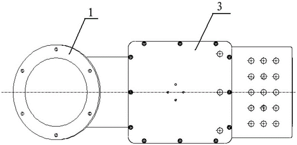
[0025] The structure of the exhaust and anti-wave anti-water device is as follows: figure 1 As shown, it includes an exhaust elbow 1, an anti-wave shell 3, a sleeve 7, a slide pipe 2, a water baffle 5 and a float 6, and the peripheral equipment is an exhaust pipe 8 of an underwater vehicle.

[0026] Since the exhaust temperature of the aircraft is as high as 450°C, and the overall weight is required to be light; therefore, the exhaust elbow 1, the sliding pipe 2, the anti-wave shell 3, the water retaining 5 and the sleeve 7 are all made of light-weight high-temperature-


PUM


Abstract

The invention provides an exhausting wave-resistant water stop device. The wave-resistant and water stop functions on an exhausting pipeline can be achieved and water can be prevented from entering equipment from the exhausting pipeline. The exhausting wave-resistant water stop device comprises an exhaust elbow, a wave-resistant shell, a hinge, a sliding mechanism, a water baffle and a floater, and peripheral equipment is an exhaust pipe. A mounting hole used for being connected with an exhaust port of the exhaust pipe is formed in the right side surface of a protective cover, an exhaust hole is formed in the arc surface, and one end of the exhaust hole is connected with the water baffle through the hinge. The floater and a guiding mechanism are located in the protective cover, and the end face of one side of the floater is tightly attached to the end face A of the protective cover. When water enters the protective cover from an opening in the bottom surface of the protective cover, the floater floats along the sliding mechanism so as to block off the exhaust port.

Description


Claims


Application Information

Patent Timeline
Owner 710TH RES INST OF CHINA SHIPBUILDING IND CORP
Why Eureka
Try Eureka