Traction bracket of foam plate surface napping machine

The technology of foam board and hair pulling machine is applied in the field of traction bracket, which can solve the problems of occupying space, unable to pull the board, large volume, etc., and achieve the effects of reducing production cost, simple production process and simple installation.

Inactive Publication Date: 2016-02-24
NANJING OURGREEN ENERGY SAVING TECH
View PDF0 Cites 0 Cited by
  • Summary
  • Abstract
  • Description
  • Claims
  • Application Information

AI Technical Summary

Problems solved by technology

The existing sheet surface roughening machines usually use an independent system, which cannot realize the direct roughening of the plate on a production line, which affects the production efficiency a

Method used


Image

  • Traction bracket of foam plate surface napping machine

Examples


Embodiment Construction

[0013] The present invention will be further explained below in conjunction with the drawings.

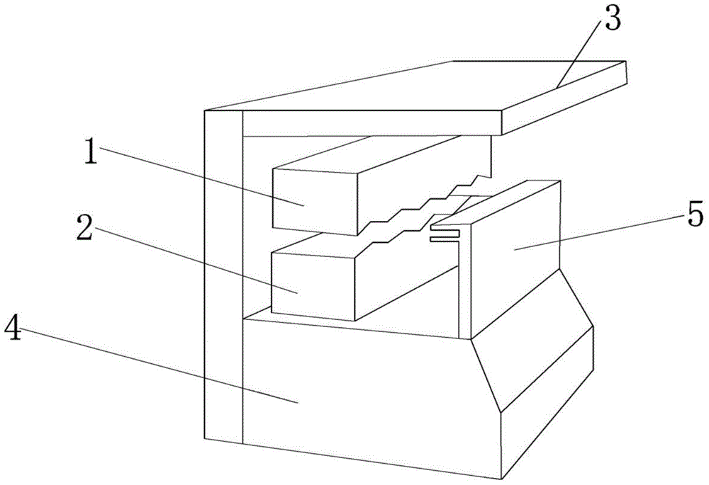
[0014] Such as figure 1 As shown, a traction support for a foam board surface napping machine is characterized in that it includes a host 4, a top baffle 3, a planer set, a traction support 5 and a motor set;

[0015] The motor unit includes a top motor and a traction motor; it is placed in the top baffle 3, and the traction motor is located at the bottom of the host 4; the traction motor is connected to the traction support 5,

[0016] The traction support 5 includes a movable plate and two traction clips; the movable plate is placed on the platform of the host 4, and the traction motor controls the movable plate to move back and forth along the foam board movement direction; the movable plate has a traction clip fixing groove; The clamp is fixed on the side of the movable plate near the planer group and forms an "F" shape with the movable plate.

[0017] The traction clamp includes an uppe


PUM


Abstract

The invention relates to a traction bracket of a foam plate surface napping machine. The traction bracket is characterized by comprising a host machine, a top portion baffle, a planing cutter group, a traction bracket and a motor group, wherein the motor group comprises a top portion motor and a traction motor and is arranged inside the top portion baffle, the traction motor is positioned on the bottom portion of the host machine, the traction motor is connected to the traction bracket, the traction bracket comprises a movement plate and two traction clampers, the movement plate is placed on the platform of the host machine, the traction motor controls the movement plate to move back and forth along the foam plate movement direction, the movement plate is provided with a traction clamper fixation groove, the traction clamper is fixed on one movement plate side close to the planing cutter group, and the traction clamper and the movement plate form F shape. According to the present invention, with the design of the traction plate, the size of the traction device can be substantially reduced, and the production cost is reduced; and the traction clamper having the adjustable size is suitable for the form plates with a variety of sizes, the adjusting can be performed according to the requirement, the traction plate is not required to be replaced, the installation is simple, and the production process is simple.

Description


Claims


Application Information

Patent Timeline
Owner NANJING OURGREEN ENERGY SAVING TECH
Why Eureka
Try Eureka