Air conditioner indoor unit

A technology for air-conditioning indoor units and centrifugal fans, applied in air-conditioning systems, space heating and ventilation, household heating, etc., can solve the problems of delayed cooling and heating effects, inability to adjust the wind direction, uneven heating and cooling, etc., to improve comfort Sexual experience, improved overall uniformity, and faster flow effects

Active Publication Date: 2016-03-02
QINGDAO HAIER AIR CONDITIONER GENERAL CORP LTD
View PDF5 Cites 7 Cited by
  • Summary
  • Abstract
  • Description
  • Claims
  • Application Information

AI Technical Summary

Problems solved by technology

[0004] However, this kind of air conditioner indoor unit cannot adjust the wind direction during use, so that the air conditioner cannot evenly blow cold or hot air to all angles of the room, resulting in deviations in temperature between the central area where the air outlet of the air conditioner is facing and other surrounding areas, and the entire room is cold. uneven heat
At the same time, the wind sent by the air conditioner tends to gather towards the central area. Therefore, if the user is in the central area, he will feel uncomfortable due to being blown directly by the wind, while other areas outside the central area will feel uncomfortable. There is a delay in cooling and heating effects

Method used


Image

  • Air conditioner indoor unit
  • Air conditioner indoor unit
  • Air conditioner indoor unit

Examples


Example Embodiment

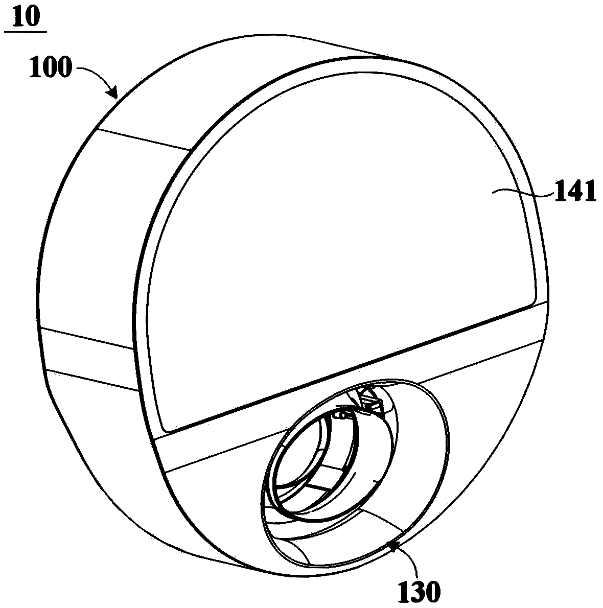
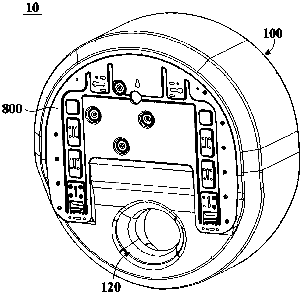
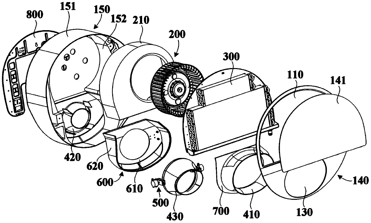
[0044] figure 1 Is a schematic structural diagram of an indoor unit of an air conditioner according to an embodiment of the present invention, figure 2 It is a schematic structural diagram of another aspect of an air conditioner indoor unit according to an embodiment of the present invention, image 3 Is a schematic structural exploded view of an indoor unit of an air conditioner according to an embodiment of the present invention, Figure 4 It is a schematic structural cross-sectional view of an indoor unit of an air conditioner according to an embodiment of the present invention. See figure 1 with figure 2 The air conditioner indoor unit 10 of the embodiment of the present invention includes a casing 100, a centrifugal fan 200 and a heat exchanger 300 located in the casing 100. The housing 100 has a heat exchange air inlet 110 and a non-heat exchange air inlet 120 for introducing air (for example, indoor air) in an environmental space, and a mixed air outlet 130 for delivering m


PUM


Abstract

The invention relates to an air conditioner indoor unit. The air conditioner indoor unit comprises a shell provided with a heat exchanged air inlet, a non-heat exchanged air inlet and a mixed air outlet, a centrifugal fan located in the shell, a heat exchanger in the shell and a drainage air guiding device arranged in the shell. The drainage air guiding device comprises at least three air guiding rings penetrating through the front and back. The at least three air guiding rings are sequentially arranged in the front-back direction to form a through air channel which penetrates through the at least three air guiding rings. The through air channel is communicated with the non-heat exchanged air inlet and the mixed air outlet. A heat exchanging air channel is formed between the two adjacent air guiding rings to guide heat exchanged air from the heat exchanged air inlet and subjected to heat exchange through the heat exchanger to the through air channel and mix the heat exchanged air with natural air from the non-heat exchanged air inlet, and then blow out the mixed air through the mixed air outlet. The at least one air guiding ring located in the middle is arranged to be movable in the front-back direction, and the air supplying direction of the mixed air outlet is adjusted by changing the size of the heat exchanging air channels between the two adjacent air guiding rings, so that the air supplying range of the air conditioner indoor unit is enlarged.

Description


Claims


Application Information

Patent Timeline
Owner QINGDAO HAIER AIR CONDITIONER GENERAL CORP LTD
Why Eureka
Try Eureka