Shielding structure for medium-voltage cable

A shielding structure and cable shielding technology, which is applied in the direction of power cables, power cables with shielding layers/conductive layers, cables, etc., can solve problems such as not making corresponding requirements, and achieve increased shielding cross-sectional area, improved shielding effect, Effect of reducing quantity to use

Active Publication Date: 2016-04-13
浙江五丰电缆有限公司
View PDF5 Cites 1 Cited by
  • Summary
  • Abstract
  • Description
  • Claims
  • Application Information

AI Technical Summary

Benefits of technology

This patented technology describes different ways for making cables with better electrical performance than previously possible due to its use of various layers that help protect them against external factors like water vapor and other gases. These techniques include adding extra materials such as metal foils (metallic coatings) between certain parts of the cable's conductor core material, create specific patterns made up of thin films of metals attached to it, reducing impedance at high frequencies while still allowing enough space around each part inside to allow more turns without cutting off any unwanted portions of the signal transmission path. Additionally, adjustments are provided during manufacturing processes where the cable needs to have multiple layers - including an outer wrap layer covering the edges of the covered coating, a laminate wrapped onto itself, and another inner wrappage called a nonwoven cloth. Overall, this design helps maintain good quality signals transmitted through these cables even when exposed to harsh environments over time.

Problems solved by technology

This patents describes different ways to protect electric conductive lines used in larger cranial devices like long distance transmission systems such as telecommunication networks. These techniques include using metal plugs covered by magazines made of nonmetallic materials called shaped weldings, which have small open spaces around their edges. To achieve this, they require closely packaging multiple layers together without leaving gaps where other parts may affect the performance of these connections. Additionally, when considering the design of the device under consideration, some technical means aim to ensure good thermal isolating properties while also reducing the risk of induced currents caused by nearby electronic equipment.

Method used


Image

  • Shielding structure for medium-voltage cable
  • Shielding structure for medium-voltage cable

Examples


Embodiment 1

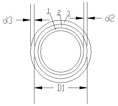
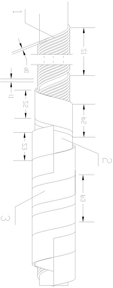
[0037] A medium-voltage cable shielding structure, the medium-voltage cable is a 26 / 35 / 40kv XLPE insulated power cable, its specification: the number of cores × section (mm2) is 1 × 500, and its conductor structure: number / unit The diameter (n / mm) is 61 / 3.20, and the outer diameter (mm) before shielding is 51.3. The shielding structure consists of three layers, which are sequentially provided with a copper wire sparse winding layer, a copper tape wrapping layer, and a non-woven fabric wrapping layer from the inside to the outside;

[0038] The copper wire sparse winding layer is formed by sparsely winding copper wires with a number of 60 and a diameter of 1.03mm. The spacing between the copper wires is 2.3 mm, and the open pitch of the copper wires is 213.6 mm.

[0039] The copper tape shielding layer is formed by wrapping a copper tape with a thickness of 0.1 mm and a width of 40 mm. The wrapping direction of the copper tape is leftward, and the outer diameter of the

Embodiment 2

[0042] A medium-voltage cable shielding structure, the medium-voltage cable is a 26 / 35 / 40kv XLPE insulated power cable, its specification: the number of cores × section (mm2) is 1 × 630, and its conductor structure: number / unit The diameter (n / mm) is 61 / 3.65, and the outer diameter (mm) before shielding is 54.9; the shielding structure consists of three layers, from the inside to the outside, there are copper wire sparse winding layer, copper tape wrapping layer, no Spun cloth around the wrapping.

[0043] The copper wire sparse winding layer is formed by copper wires with a number of 64 and a diameter of 1.03 mm. The copper wires are sparsely wound in the right direction, and the outer diameter of the sparse winding is 57.0 mm. Every two adjacent The spacing between the copper wires is 3.1 mm, and the open pitch of the copper wires is 247.9 mm.

[0044] The copper tape shielding layer is formed by wrapping a copper tape with a thickness of 0.1 mm and a width of 40 mm.

Embodiment 3

[0047] A medium-voltage cable shielding structure, the medium-voltage cable is a 26 / 35 / 40kv XLPE insulated power cable, its specification: the number of cores × section (mm2) is 1 × 500, and its conductor structure: number / unit The diameter (n / mm) is 61 / 3.20, and the outer diameter (mm) before shielding is 51.3. The shielding structure consists of three layers, which are sequentially provided with a copper wire sparse winding layer, a copper tape wrapping layer, and a non-woven fabric wrapping layer from the inside to the outside;

[0048] The copper wire sparse winding layer is formed by sparsely winding copper wires with a number of 60 and a diameter of 1.03mm. The distance between the copper wires is 4 mm, and the pitch of the copper wires is 320.4 mm.

[0049] The copper tape shielding layer is formed by wrapping a copper tape with a thickness of 0.1 mm and a width of 40 mm. The wrapping direction of the copper tape is leftward, and the outer diameter of the copper


PUM

PropertyMeasurementUnit
Diameteraaaaaaaaaa
Outer diameteraaaaaaaaaa

Abstract

The invention relates to a shielding structure for a medium-voltage cable. The shielding structure sequentially comprises a copper-wire sparse winding layer, a copper strip wrapping layer and a nonwoven wrapping layer from the inside to the outside, wherein the copper-wire sparse winding layer is formed by sparse winding of n copper wires of which the diameters are d1; the sparse winding direction of the copper wires is toward the right; the distance between every two adjacent copper wires is l1; the sparse winding pitches of the copper wires are S1; the sparse winding outside diameter is D1; the copper strip wrapping layer is formed by wrapping a copper strip of which the thickness is d2 and the width is b2; the wrapping direction of the copper strip is toward the left; the wrapping pitch of the copper strip is S2; the nonwoven wrapping layer is formed by wrapping a layer of nonwoven of which the thickness is d3 and the width is b3; the wrapping direction of the nonwoven is toward the right; the wrapping pitch of the nonwoven is S3, wherein d1 is 1.03mm; l1 is smaller than or equal to 4mm; S1 is smaller than or equal to 6D1 and greater than or equal to (n-1)*l1+2*d1; d2 is 0.1mm; b2 is 40mm; S2 is smaller than or equal to b2 and greater than or equal to b2/3; d3 is 0.2mm; b3 is 50mm; and S3 is 32mm. The shielding inhibition coefficient is reduced through optimizing the structures of the copper-wire sparse winding layer, the copper strip wrapping layer and the nonwoven wrapping layer in a shielding layer, so that the shielding effect of the shielding layer is improved.

Description


Claims


Application Information

Patent Timeline
Owner 浙江五丰电缆有限公司
Why Eureka
Try Eureka