Fixing structure for decorative material layer

A decorative material and fixed structure technology, applied in building construction, covering/lining, construction, etc., can solve problems such as inconvenient installation and complex structure, achieve the effect of simple and convenient use, ingenious and light structure, and reduce the chance of falling off

Active Publication Date: 2016-04-20
徐州市通途装配式建筑科技有限公司
View PDF6 Cites 1 Cited by
  • Summary
  • Abstract
  • Description
  • Claims
  • Application Information

AI Technical Summary

Problems solved by technology

Although the above-mentioned technical scheme can securely fix the decorative material layer on the exterior wall of the building to a certain extent, its structure is relatively complicated, and there are many inconveniences in installation, which needs to be improved urgently.

Method used


Image

  • Fixing structure for decorative material layer
  • Fixing structure for decorative material layer
  • Fixing structure for decorative material layer

Examples


Embodiment 1

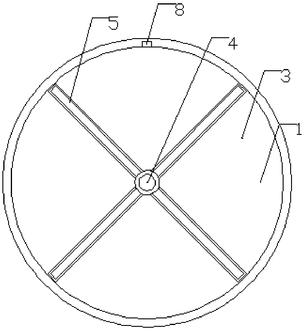
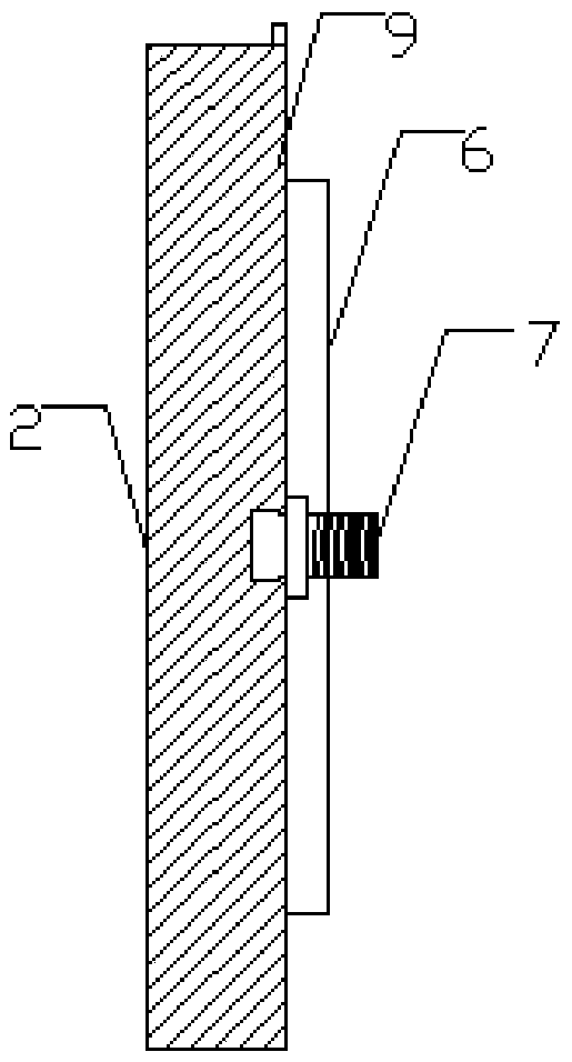
[0032] Such as figure 1 , figure 2 and image 3 As shown, a fixed structure of a decorative material layer includes: a building exterior wall 1 and a circular decorative material layer 2 matching the building exterior wall 1, and the building exterior wall 1 is provided with a The groove 3 of the layer 2 is provided with a threaded installation groove 4 on the inner wall in the center of the groove 3, and a plurality of card grooves 5 are also arranged around the installation groove 4 in the groove 3. The decorative material layer 2 The side matching the groove 3 is provided with a card strip 6 matching the card groove 5, and a receiving block 7 is movably connected in the center of the decorative material layer 2, and it can move axially along the receiving block 7 so that The clamping strip 6 is engaged with the clamping groove 5 in one-to-one correspondence, and the end of the receiving block 7 close to the groove 3 is provided with an external thread that matches the mo...

Embodiment 2

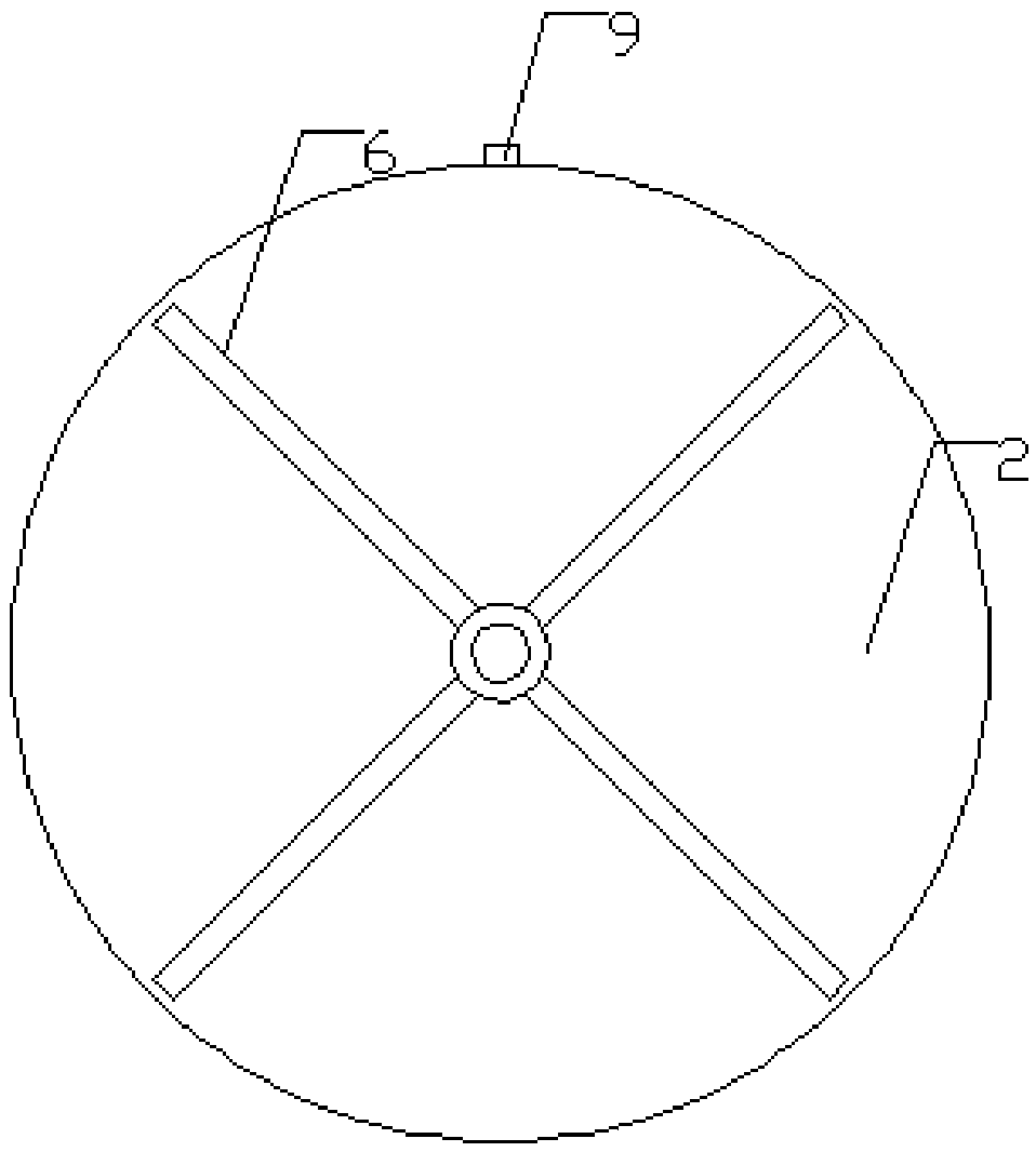
[0036] Such as Figure 4 , Figure 5 and Figure 6 As shown, a fixed structure of a decorative material layer includes: a building exterior wall 1 and a circular decorative material layer 2 matching the building exterior wall 1, and the building exterior wall 1 is provided with a The groove 3 of the layer 2 is provided with a threaded installation groove 4 on the inner wall in the center of the groove 3, and a plurality of card grooves 5 are also arranged around the installation groove 4 in the groove 3. The decorative material layer 2 The side matching the groove 3 is provided with a card strip 6 matching the card groove 5, and a receiving block 7 is movably connected in the center of the decorative material layer 2, and it can move axially along the receiving block 7 so that The clips 6 are snapped together with the slots 5 one by one, the end of the receiving block 7 close to the groove 3 is provided with an external thread matching the installation groove 4, and the deco...


PUM


Abstract

The invention relates to a fixing structure for a decorative material layer. The fixing structure comprises an external building wall and the circular decorative material layer. The circular decorative material layer is matched with the external building wall, a groove capable of accommodating the decorative material layer is formed in the external building wall, a mounting groove is formed in the center of the groove, threads are arranged on the inner wall of the mounting groove, a plurality of clamp grooves are further formed in the groove and encircle the mounting groove, clamp strips which are matched with the clamp grooves are arranged on the side, which is matched with the groove, of the decorative material layer, a carrying block is movably connected to the center of the decorative material layer, and the decorative material layer can axially move along the carrying block, so that the clamp strips and the clamp grooves can be fastened with one another in a one-to-one correspondence manner; external threads matched with the mounting groove are arranged at the end, which is close to the groove, of the carrying block. Compared with the prior art, the fixing structure has the advantages that the fixing structure is ingenious and light and can be used easily, conveniently and quickly.

Description

technical field [0001] The invention belongs to the technical field of decoration material installation, and in particular relates to a fixing structure of a decoration material layer. Background technique [0002] At present, when fixing the decorative material layer on the outer wall of the building, the method often used in construction is to first fix the steel keel on the wall, then fix the stone with wire drawing, and finally pour grout as bonding. After a period of time in this way, the stone material will fall off, which is unsightly from an aesthetic point of view, and from a safety point of view, it will affect passing pedestrians and vehicles. [0003] In order to solve the above-mentioned technical problems, patent ZL201220127934.8 discloses a fixing structure for a decorative material layer, which includes a flat layer, and several convex lines are arranged on both sides of the flat layer. The groove corresponding to the convex strip, the flat layer is connecte...

Claims


Application Information

Patent Timeline
IPC IPC(8): E04F13/24
CPCE04F13/0835
Inventor 卢俊峰
Owner 徐州市通途装配式建筑科技有限公司
Why Eureka
Try Eureka