POE controller and POE control system

A control system and controller technology, applied in the direction of data exchange details, data switching current source, etc., can solve the problems of LAN cables that cannot be installed, POE control system is limited, etc., and achieve the effect of reducing the number

Inactive Publication Date: 2016-04-27
ESPOT LIGHTING
View PDF5 Cites 2 Cited by
  • Summary
  • Abstract
  • Description
  • Claims
  • Application Information

AI Technical Summary

Problems solved by technology

However, in some practical situations, LAN cables cannot be installed
[0004] In addition, in the prior art, one POE controller in the POE control s

Method used


Image

  • POE controller and POE control system
  • POE controller and POE control system

Examples


Embodiment Construction

[0031] In order to make the purpose, technical solutions and advantages of the embodiments of the present invention clearer, the technical solutions in the embodiments of the present invention will be clearly and completely described below in conjunction with the drawings in the embodiments of the present invention. Obviously, the described embodiments It is a part of embodiments of the present invention, but not all embodiments. Based on the embodiments of the present invention, all other embodiments obtained by persons of ordinary skill in the art without making creative efforts belong to the protection scope of the present invention.

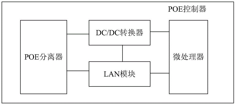
[0032] An embodiment of the present invention provides a POE controller, figure 1 A schematic structural diagram of the POE controller is shown. The POE controller includes a POE splitter, a DC / DC converter, a LAN module and a microprocessor.

[0033] The POE power supply system can also provide DC power supply for these terminals while tran


PUM


Abstract

The embodiment of the invention provides a POE controller and a POE control system; a POE controller adopts a PWM terminal or a DC voltage terminal; the POE controller comprises a POE separator which is used for separating the DC voltage and the data, a DC/DC converter which is connected to the POE seperator, and an LED lamp which is used for converting DC voltage supplied by the POE seperator to DC high voltage and supplying the DC high voltage to an LED lamp driven by the DC voltage; the DC voltage supplied by the POE seperator is converted to the DC low voltage which is supplied to the microprocessor; an LAN module is connected to the POE seperator and the DC/DC converter; the LAN module is used for receiving the data coming from the POE seperator and transmitting the data to the microprocessor; the microprocessor is connected to the DC/DC converter and the LAN module for executing the data coming from the LAN module and generating a corresponding control signal to control the LED lamp.

Description


Claims


Application Information

Patent Timeline
Owner ESPOT LIGHTING
Why Eureka
Try Eureka