Glass fixture

A glass fixture and angle technology, applied in the field of clamping tooling, can solve problems such as unfavorable enterprise product efficiency, affecting enterprise production efficiency, unreliable glass clamping, etc., to avoid glass vibration and wear, avoid deformation, and reduce hardness.

Inactive Publication Date: 2016-06-15
东莞市奇声电子实业有限公司
View PDF7 Cites 2 Cited by
  • Summary
  • Abstract
  • Description
  • Claims
  • Application Information

AI Technical Summary

Problems solved by technology

Among them, during the cleaning process, the glass will vibrate to a certain extent under the action of external force. Therefore, it is not possible to use rigid or hard fixtures during the cleaning process, otherwise the glass will be worn during the vibration; however, in During the tempering process, the glass will be in a high-temperature processing environment. Therefore, fixtures with strong rigidity and heat resistance are required during the tempering process, otherwise the fixtures will be deformed and the glass clamping will be unreliable.
At present, enterprises need to use two different fixtures in the two processes of cleaning and tempering. Specifically, fixtures made of plastic are used in the cleaning process, and fixtures made of steel are used in the tempering process to meet the needs of the two processes. Different processing requirements, therefore, the fixture needs to be replaced after glass cleaning, and then tempering can be carried out. This operation seriously affects the production efficiency of the enterprise and is not conducive to the enterprise to improve product efficiency

Method used


Image

  • Glass fixture
  • Glass fixture
  • Glass fixture

Examples


Example Embodiment

[0045] Embodiment one:

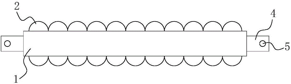
[0046] like figure 1 and figure 2 As shown, a glass fixture is characterized in that it includes an installation shaft 1 and a stop tooth, the stop tooth is fixedly arranged on the outer surface of the installation shaft 1, and the stop tooth is made of copper. The centerline of the installation shaft 1 is a straight line. The hardness of the limit teeth made of copper is lower than that of steel teeth, which can avoid glass vibration wear during cleaning. At the same time, the heat resistance of the limit teeth made of copper is stronger than that of plastic teeth, which can avoid Deformation during tempering process ensures clamping reliability.

[0047] In this embodiment, the stop teeth include two sets of first stop teeth 2 arranged symmetrically, and the included angle between the two groups of first stop teeth 2 is 180 degrees. The shape of the first limiting tooth 2 is sinusoidal.

[0048] In this embodiment, the installation shaft 1 is made

Example Embodiment

[0050] Embodiment two:

[0051] The difference between this embodiment and Embodiment 1 is:

[0052] like image 3 and Figure 4 As shown, the limiting teeth include two groups of symmetrically arranged first limiting teeth 2, and the angle between the two groups of first limiting teeth 2 is 180 degrees. The first limiting tooth 2 includes several semicircular rods connected in sequence, and the opening directions of the several semicircular rods are the same. The mounting shaft 1 is made of steel.

Example Embodiment

[0053] Embodiment three:

[0054] The difference between this embodiment and Embodiment 1 is:

[0055] like Figure 5 and Image 6As shown, the limiting teeth include two groups of symmetrically arranged first limiting teeth 2, and the angle between the two groups of first limiting teeth 2 is 180 degrees. The first limiting tooth 2 includes several V-shaped rods connected in sequence, and the opening directions of the several V-shaped rods are the same. The installation shaft 1 is a cuboid, and two groups of the first limiting teeth 2 are respectively arranged on two opposite sides of the cuboid.


PUM


Abstract

The invention relates to the technical field of clamping tooling, and discloses a glass fixture, which includes a mounting shaft and a limiting tooth, the limiting tooth is fixedly arranged on the outer surface of the mounting shaft, and the limiting tooth is made of copper. The present invention uses copper as the manufacturing material of the stop teeth, on the one hand, reduces the hardness of the stop teeth to a certain extent, avoids glass vibration and wear, and makes the glass fixture meet the use requirements of the cleaning process; The amount of deformation in the high temperature environment enables the glass fixture to meet the requirements of the tempering process, thereby omitting the fixture replacement operation between the two processes, improving production efficiency, effectively reducing the types of fixtures, and reducing the manufacturing and maintenance costs of fixtures .

Description


Claims


Application Information

Patent Timeline
Owner 东莞市奇声电子实业有限公司
Why Eureka
Try Eureka