Air duct blade device used for vehicle

A vehicle and air duct technology, applied in the field of wind energy utilization devices on vehicles, can solve the problems of increased use and maintenance costs, unutilized wind resources, etc., and achieve the effect of increasing wind speed

Inactive Publication Date: 2016-06-15
QINGDAO JINZHI HIGH NEW TECH
View PDF3 Cites 0 Cited by
  • Summary
  • Abstract
  • Description
  • Claims
  • Application Information

AI Technical Summary

Benefits of technology

This invention relates to an improved design for vehicles that uses multiple shaping structures called bells or tunnels at one side of their body. These designs help improve energy efficiency by allowing more winds into them while reducing resistance from being forced through other parts of the car's chassis due to lower levels of force on certain areas caused by turbulence during driving conditions.

Problems solved by technology

This patents discusses improving both the efficiency and effectiveness of an electricity collector system used for vehicles' charging purposes. However, current systems are often less efficient or require more expensive equipment due to their fixed position relative to certain factors such as road conditions and traffic patterns.

Method used


Image

  • Air duct blade device used for vehicle
  • Air duct blade device used for vehicle

Examples


Embodiment Construction

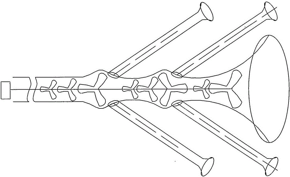
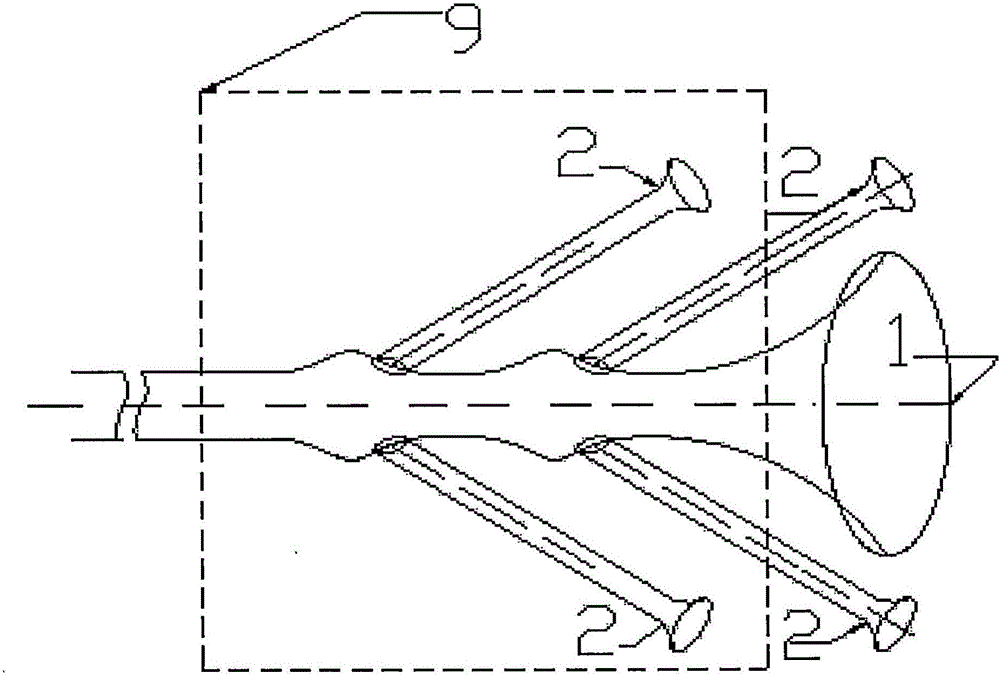
[0011] 1. Working principle

[0012] 1) Wind flow Q = area of ​​air inlet section A * wind speed V

[0013] 2) Wind pressure F = wind speed V square / 1600 (under one atmospheric pressure under standard conditions, the temperature is 15 degrees, and the air density = 0.01225Kg / m2)

[0014] 3) The effective power of the turbine W=Q*F

[0015] From the changes of the above three formulas, the following results can be obtained theoretically: changing the area A of a certain section in the air duct can change the wind speed. When the area A of the cross-section is reduced by half, the wind speed is doubled and the effective power is increased by four times.

[0016] 2. Design

[0017] 1. Analyze the driving data of the installed vehicle, the shape of the vehicle, and the parts subjected to wind resistance, and determine the size, shape and size, shape and quantity of the bell mouth.

[0018] 2. Determine the specifications and quantities of different wind rotors according to


PUM


Abstract

The invention provides an air duct blade device used for a vehicle and relates to devices for applying wind energy to vehicles. The air duct blade device used for the vehicle aims at converting a wind resource affecting the vehicle resistance into electric energy or mechanical energy through an air duct formed by combining structures in many shapes within a limited space. According to the air duct blade device used for the vehicle, the air duct blade device is connected with a generator and other using devices through the air duct formed by combining the structures in many shapes, a wind wheel, a center transmission shaft, a bracket, a controller and the like, so that the onward journey kilometer of the vehicle provided with the air duct blade device is dramatically increased.

Description


Claims


Application Information

Patent Timeline
Owner QINGDAO JINZHI HIGH NEW TECH
Why Eureka
Try Eureka