Liquid treatment cartridge, set of such cartridges and method of manufacturing it

A liquid treatment, liquid technology, applied in the field of liquid treatment cores

Active Publication Date: 2016-07-13
BRITA GMBH
View PDF15 Cites 7 Cited by
  • Summary
  • Abstract
  • Description
  • Claims
  • Application Information

AI Technical Summary

Benefits of technology

The present technology allows for more efficient use of space by dividing different parts within multiple chambers into smaller spaces that can communicate with each others through flowing fluids or gas instead of just allowing them separately. This helps improve efficiency without taking up too much room on top of it's own design.

Problems solved by technology

Technic problem: Current devices used for treatment have limitations such as requiring multiple connections per unit time (performance) due to their design flaw. Additionally, current designs require specific parts like filters and holders, making them difficult to manufacture efficiently while also meeting performance requirements.

Method used


Image

  • Liquid treatment cartridge, set of such cartridges and method of manufacturing it
  • Liquid treatment cartridge, set of such cartridges and method of manufacturing it
  • Liquid treatment cartridge, set of such cartridges and method of manufacturing it

Examples


Embodiment Construction

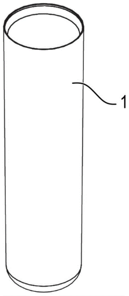
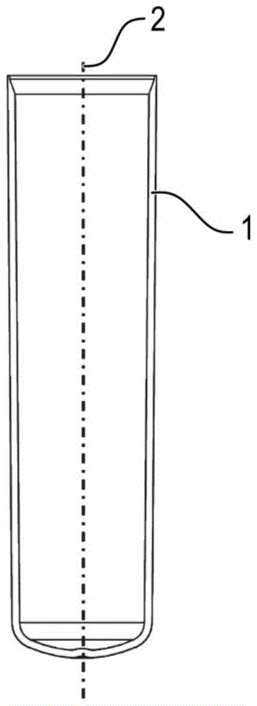
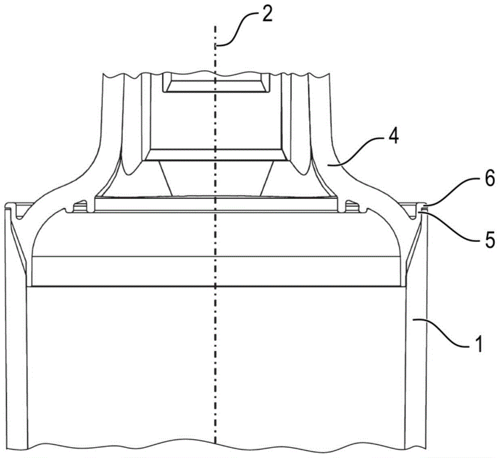
[0129] The liquid handling core as described below comprises a housing comprising a container in the form of a beaker-shaped housing part 1 ( Figure 1-3 , Figure 22 , Figure 36-39 ). The beaker-shaped housing part 1 is elongated in shape. The central axis 2 (in this example the longitudinal axis 2 ( figure 2 , image 3 )) form the reference axis. The beaker-shaped housing part 1 is closed at one axial end and open at the opposite axial end. The beaker-shaped housing part 1 is substantially cylindrical along most of its length. The closed axial end is rounded to withstand the pressure of the liquid in the beaker-shaped housing part 1 during use. The beaker-shaped housing part 1 can be made of metal such as aluminum or plastic such as polypropylene. The open end of the beaker-shaped housing part 1 is closed by and irreversibly bonded to the hat-shaped housing part.

[0130] The first hat-shaped housing part 3 ( Figure 3-21 ) comprises a main body 4, which can be obta


PUM


Abstract

A liquid treatment cartridge includes a housing, the housing including a housing part forming an axial end of the housing and including a connecting head at the axial end of the housing. The connecting head includes at least three liquid ports, each at an end of a respective channel defined by the housing part. The connecting head is configured for insertion into a head part of a liquid treatment system such that the liquid ports of the connecting head are in sealed liquid communication with respective liquid ports in the head part. The liquid treatment cartridge includes at least one separate flow conductor part on the inside of the housing, attached to the housing part and including at least one conduit for conducting liquid so as to separate interior ends of at least two of the channels from those of at least one other of the channels. The at least three liquid ports at ends of respective channels defined by the housing part include at least a fourth liquid port.

Description


Claims


Application Information

Patent Timeline
Owner BRITA GMBH
Why Eureka
Try Eureka