Structure of push-and-pull fan made of composite material

A composite material and longitudinal axis technology, which is applied to the layout of the wings, the frame of the wings, and building components, etc., can solve the problems of insufficient wind pressure resistance and airtightness, and achieve good general performance of the window sash, beautiful functions, and low consumables Effect

Inactive Publication Date: 2016-07-27
SHANGHAI COLLODIN MATERIAL TECH DEV CO LTD +1
View PDF6 Cites 0 Cited by
  • Summary
  • Abstract
  • Description
  • Claims
  • Application Information

AI Technical Summary

Benefits of technology

This new type of slide windows made from strong but flexible composites are designed for better durability without adding extra weight or requiring expensive maintenance compared to traditional metal designs that require heavy equipment like steel frames. They also have excellent weathering properties while still being able to maintain their effectiveness over time even when exposed to harsh environments such as rainwater. Overall, these technical features improve efficiency, functionality, usages, cost savings, and overall user experience during use on various types of vehicles.

Problems solved by technology

This technical problem addressed by this patented technology relates to improving heating/ventilation efficiency during winter months when air conditioners use traditional methods like blower fans to circulate warm indoor spaces through an enclosed space such as a house. However, these techniques have limitations with regards to maintaining good sealing between the frame members themselves while also providing strong support against bending forces caused from snow loads hitting it't really work properly.

Method used


Image

  • Structure of push-and-pull fan made of composite material
  • Structure of push-and-pull fan made of composite material
  • Structure of push-and-pull fan made of composite material

Examples


Embodiment 1

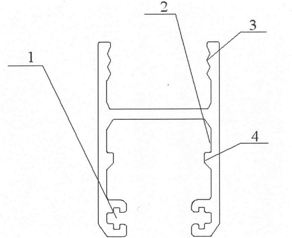
[0018] The present invention is a structure of a composite push-pull fan, such as figure 1 As shown, its cross-section is a simple "H"-shaped structure, including two opposite longitudinal axes and a transverse axis connected therebetween. Both inner sides of one end of the "H"-shaped structural profile are provided with brush grooves 1 for placing brush seals 14, and both inner sides of the other end of the "H"-shaped structure are provided with tooth grooves 3 for fixing glass 13. One end of the "H"-shaped structure is provided with a functional groove 2 at a position away from the brush groove 1. The functional groove 2 is formed by a horizontal axis and protrusions 4 on two longitudinal axes. The angle between one side of the protrusion 4 located in the functional groove 2 and the longitudinal axis is less than or equal to 90°, and the angle between the other side of the protrusion 4 and the longitudinal axis is greater than 90°.

[0019] Such as figure 2 Shown, two hairb

Embodiment 2

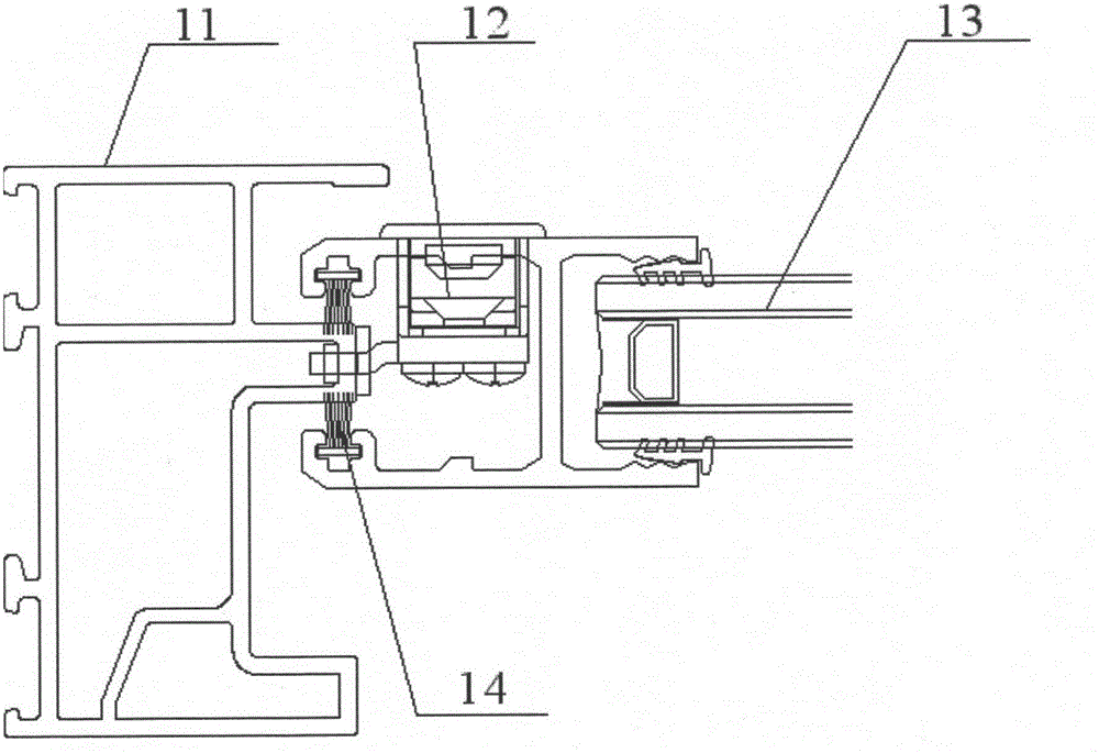
[0023] Such as image 3 Shown, two hairbrush grooves 1 of the present invention are all loaded onto hairbrush sealing strip 14, and the sealing between the hairbrush sealing strip 14 and the outer frame 11 of sliding window plays whole window sealing. A pulley 15 can be installed on the functional groove 2, so that the push-pull fan can move in the outer frame 11 through the pulley 15, and the sealing of the tooth groove 3 and the glass 13 can be inlaid and connected with a special sealing rubber strip or sealant.

[0024] Others are the same as in Example 1.

Embodiment 3

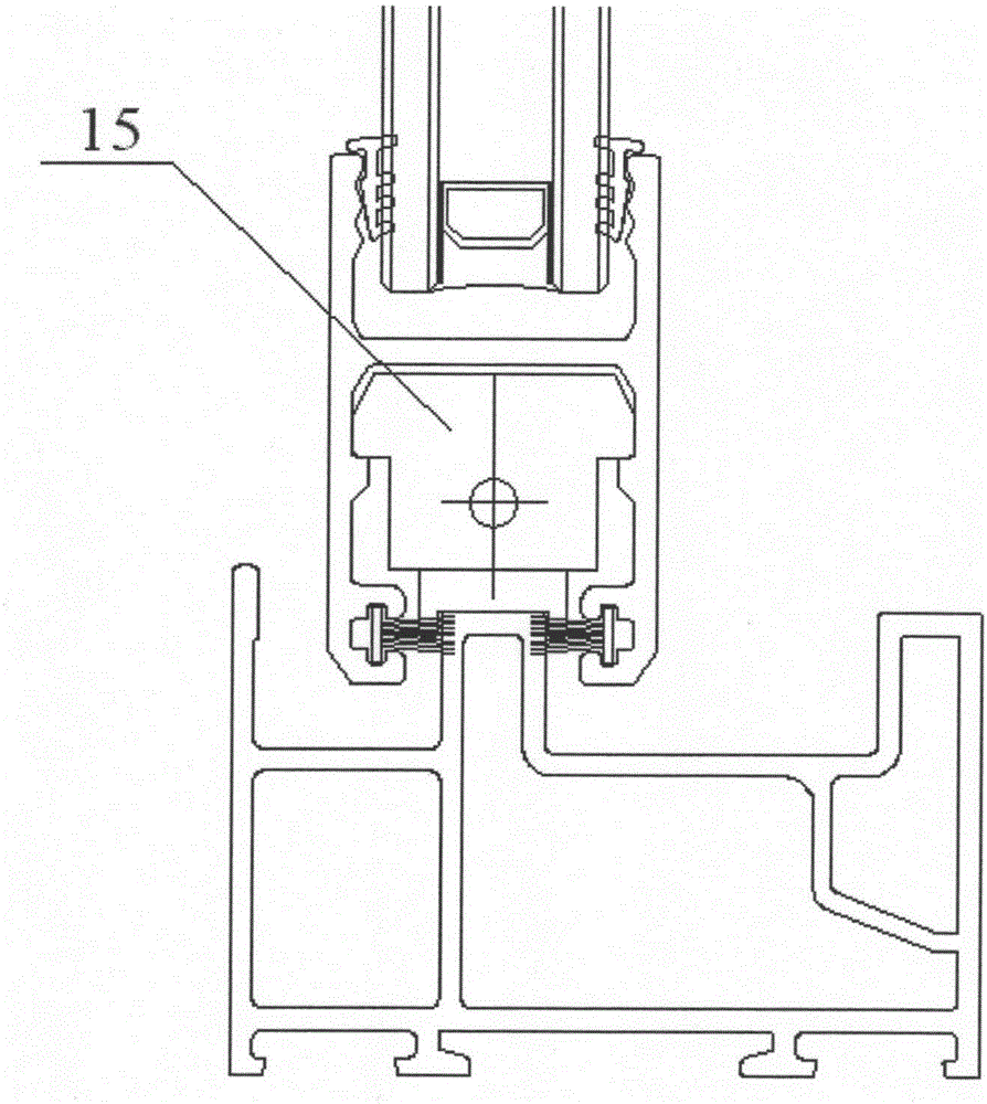
[0026] Such as Figure 4 As shown, in the functional groove 2, a fan connecting piece 16 can be installed, and a circle of the fan is assembled into one body through the fan connecting piece 16, and the tooth groove 3 and the glass 13 are hermetically connected.

[0027] Others are the same as in Example 1.


PUM


Abstract

The invention discloses a structure of a push-and-pull fan made of a composite material. The push-and-pull fan is characterized in that the section of the fan is of an H-shaped structure, brush grooves used for accommodating brush sealing strips are formed in the two inner sides of one end of the H-shaped structure, and a functional groove is formed in the position, away from the brush grooves, of one end of the H-shaped structure. The sectional material is high in universality, any portion of the whole push-and-pull fan can be made of the same sectional material, and different auxiliary parts can be installed on different portions of the fan within the sectional material; due to the high strength of the composite material, the section of the sectional material can be in a simplest shape to meet requirements for strength and airtightness.

Description


Claims


Application Information

Patent Timeline
Owner SHANGHAI COLLODIN MATERIAL TECH DEV CO LTD
Why Eureka
Try Eureka