3D glasses having disinfecting function

A technology of 3D glasses and functions, applied in the field of 3D display, can solve the problems of bacterial virus transmission, glasses cannot be disinfected in time, etc., and achieve the effect of eliminating bacteria and viruses and saving power

Inactive Publication Date: 2016-10-05
ZHEJIANG ESTAR DISPLAY TECH
View PDF5 Cites 2 Cited by
  • Summary
  • Abstract
  • Description
  • Claims
  • Application Information

AI Technical Summary

Problems solved by technology

3D glasses are small devices that can be reused, especially in public places such as movie theaters. Many customers use the same pair of glasses to watch 3D movies one after another. Since the glasses cannot be disinfected in time, many bacteria and viruses on the glasses can spread, becoming a eye killer

Method used


Image

  • 3D glasses having disinfecting function
  • 3D glasses having disinfecting function
  • 3D glasses having disinfecting function

Examples


Example Embodiment

[0021] In order to make the objectives, technical solutions, and advantages of the present invention clearer, the following further describes the present invention in detail with reference to the accompanying drawings and embodiments. It should be understood that the specific embodiments described here are only used to explain the present invention, and not to limit the present invention.

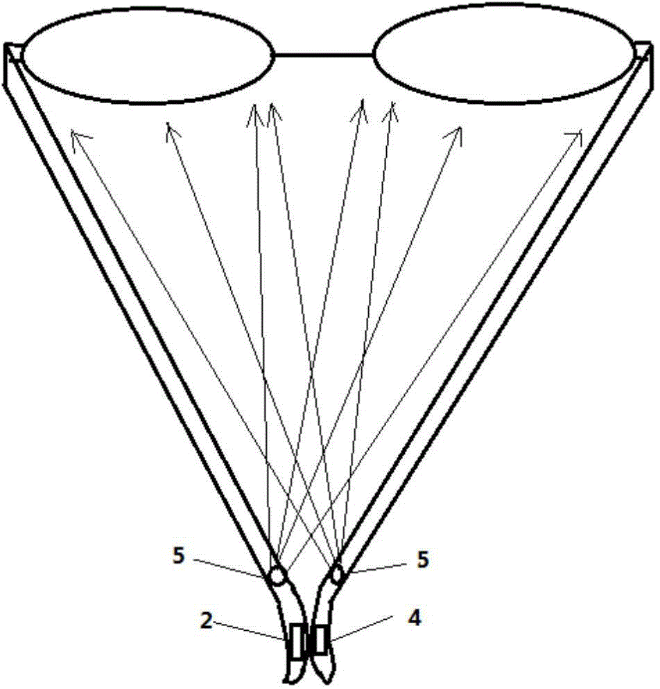
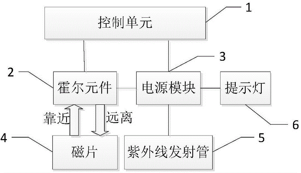
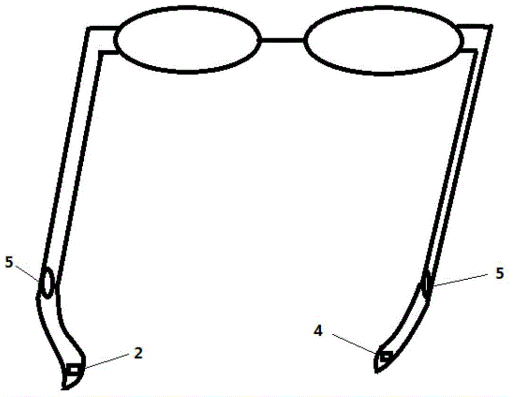
[0022] See figure 1 , figure 1 It is a connection diagram of some parts of 3D glasses with disinfection function provided by the present invention. The 3D glasses provided by the present invention include: a control unit 1, a Hall element 2, a power module 3, a magnetic sheet 4, an ultraviolet emitting tube 5 and a reminder light 6.

[0023] Wherein, the position of the Hall element 2 includes being placed on the one side of the temple, which is electrically connected to the control unit 1 and the power module 3; the position of the magnetic sheet 4 includes being placed on the On the other side o


PUM


Abstract

The invention relates to the technical field of 3D display, in particular to 3D glasses having a disinfecting function. The 3D glasses having the disinfecting function mainly comprise a control unit, a Hall element, a magnetic plate and ultraviolet ray emitting tubes. When the magnetic plate and the Hall element are in contact or close to each other, the control unit receives a high-level signal sent by the Hall element and controls a power supply module to supply power to the ultraviolet ray emitting tubes, and ultraviolet rays emitted by the ultraviolet ray emitting tubes is used for disinfecting the whole 3D glasses and surrounding parts thereof; when a viewer separates two legs of the glasses, the control unit receives a low-level signal sent by the Hall element since the magnetic plate is far away from the Hall element, and controls the power supply module to stop supplying power to the ultraviolet ray emitting tubes, thus the3D glasses are not disinfected at the moment; and the ultraviolet ray emitting tubes are arranged on the two legs of the glasses for disinfecting the glasses and eliminating bacteria and viruses on the glasses, thereby making the 3D glasses wearing process more safe and secure.

Description


Claims


Application Information

Patent Timeline
Owner ZHEJIANG ESTAR DISPLAY TECH
Why Eureka
Try Eureka