Improved middle-high voltage zero-sequence current transformer
A technology of zero-sequence current and medium-high voltage, which is applied in the field of electric power, can solve problems such as restrictions on the application and promotion of zero-sequence current transformers, and achieve the effects of improving the intelligence of the power grid, good anti-loosening effect, and labor-saving operation
- Summary
- Abstract
- Description
- Claims
- Application Information
AI Technical Summary
Problems solved by technology
Method used
Image

Examples
Example
[0019] (Example 1)
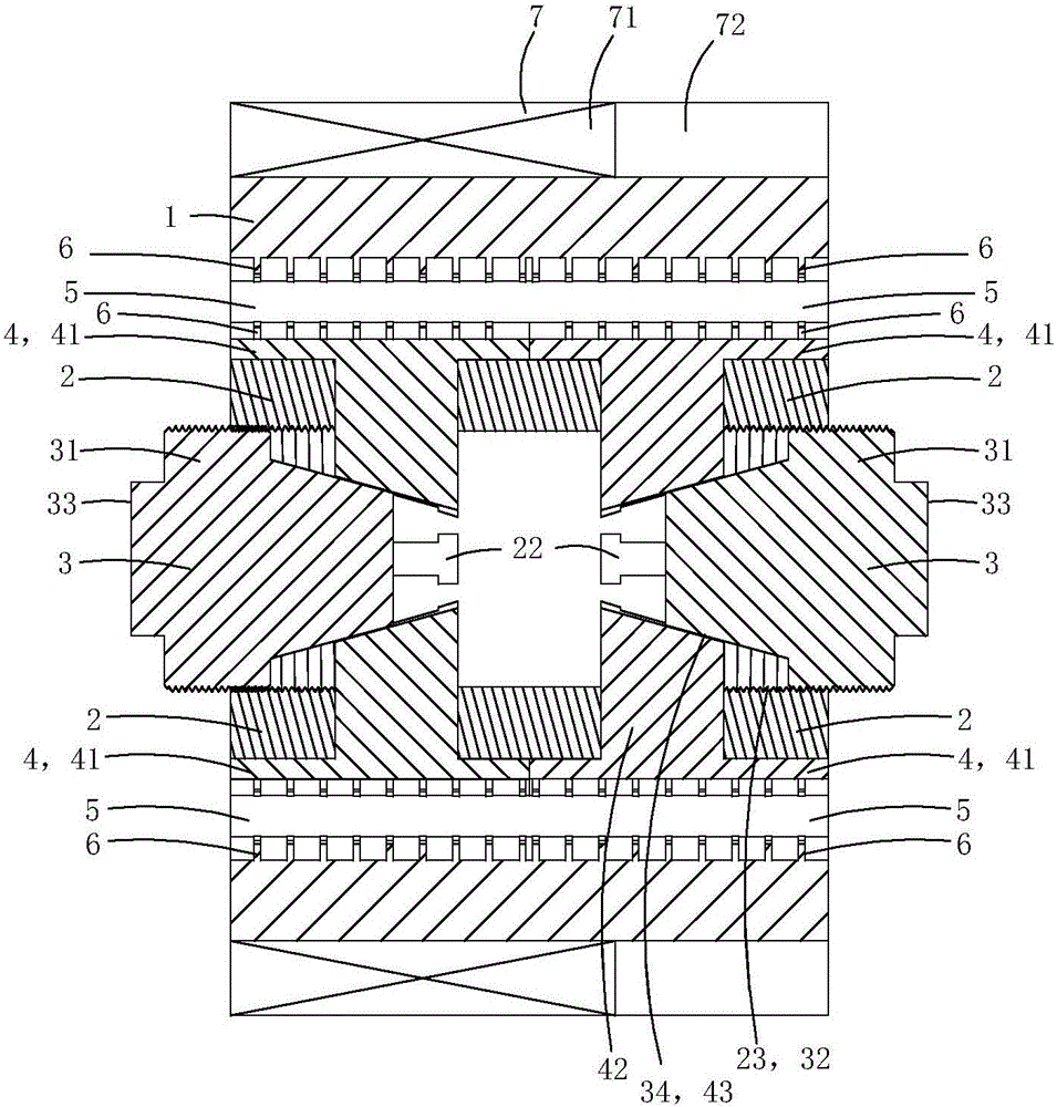
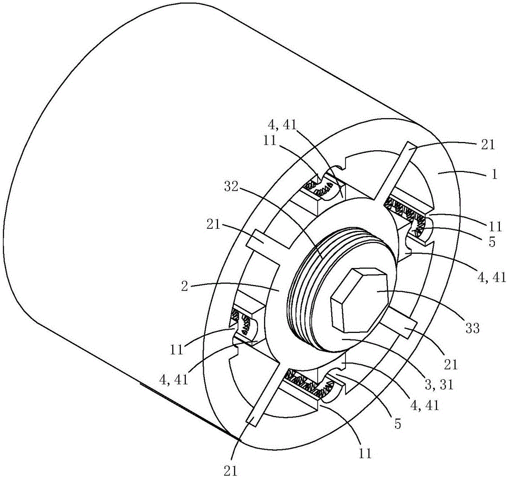
[0020] This embodiment is an improved medium and high voltage zero-sequence current transformer, see Figure 1 to Figure 6 As shown, it includes a base tube 1 , a core tube 2 , a current transformer 7 , two crimping parts 3 and two sets of crimping jaw assemblies 9 .
[0021] In this embodiment, the base pipe, the core pipe 2, the two crimping parts 3 and the two sets of pressing jaw assemblies 9 are all made of insulating materials.
[0022] The inner peripheral wall of the base pipe is provided with four clamping bosses 11, and the inner wall of each clamping boss is provided with arc-shaped grooves 111, and each wire-holding boss and arc-shaped grooves extend axially along the base pipe. The inner peripheral wall of the base pipe is also provided with a plurality of positioning sliding grooves 12 along the axial direction of the base pipe.
[0023] The core tube and the base tube are concentrically arranged, and the core tube is located in the lumen of t
Example
[0036] (Example 2)
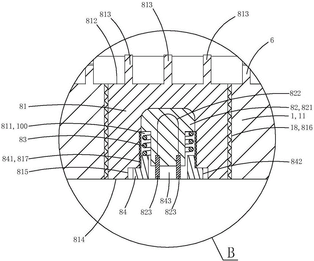
[0037] This embodiment is basically the same as Embodiment 1, the difference is: see Figure 7 and Figure 8 As shown, the base pipe 1 is provided with a mounting screw hole 18 that penetrates the wall of the clamping boss 11 along the radial direction of the base pipe; a temperature sensing device 8 is fixed in the mounting screw hole;
[0038] The temperature sensing device includes a metal housing 81 made of metal material with a containing groove 811, a temperature sensor 82 arranged in the containing groove, a spring 83 for crimping the temperature sensor on the bottom wall of the containing groove, Coil plug 84 for limit spring;
[0039] One end 812 of the metal shell close to the central axis of the base tube is provided with a heat conduction boss 813 used as a puncture, and one end 814 of the metal shell away from the central axis of the base tube is provided with an inner hexagonal screw groove 815; There is an external thread 816 adapted to the
Example
[0047] (Example 3)
[0048] This embodiment is basically the same as Embodiment 1, the difference is: see Figure 9 to Figure 10 As shown, in this embodiment, the ring-shaped inductive induction body is sleeved and fixed on the outer peripheral wall of the base tube; the outer peripheral wall of the base tube is provided with a wiring hole 13 (the position shown by the dotted line) that penetrates the tube wall in the radial direction; The wall, the outer wall of the core tube, the wire clamping boss, the supporting convex plate, and the pressure jaw pressing plate are clamped to form a plurality of accommodation cavities 73, and the intelligent control module is arranged in the accommodation cavity; between the ring-shaped induction body and the intelligent control module The electrical connection wires pass through the wiring holes. This structure can make full use of the space and is conducive to the overall small size and integration.
[0049] In addition, the base pipe 1 i
PUM
 Abstract
Description
Claims
Application Information
 - R&D Engineer
- R&D Manager
- IP Professional
- Industry Leading Data Capabilities
- Powerful AI technology
- Patent DNA Extraction
Browse by: Latest US Patents, China's latest patents, Technical Efficacy Thesaurus, Application Domain, Technology Topic.
© 2024 PatSnap. All rights reserved.Legal|Privacy policy|Modern Slavery Act Transparency Statement|Sitemap