Hydraulic cutting device for deep sea cutting sleeve

A cutting device and hydraulic technology, applied in wellbore/well components, earth-moving drilling, etc., can solve the problems of low cutting efficiency, insufficient blade life, complicated operation, etc., and achieve simple structure, convenient use and cost reduction. Effect

Active Publication Date: 2017-02-22
YANGTZE UNIVERSITY
View PDF9 Cites 4 Cited by
  • Summary
  • Abstract
  • Description
  • Claims
  • Application Information

AI Technical Summary

Problems solved by technology

However, in the currently used hydraulic cutters, due to the insufficient life of the blades, the inability to automatically retract the body after cutting, the complex structure of the t

Method used


Image

  • Hydraulic cutting device for deep sea cutting sleeve
  • Hydraulic cutting device for deep sea cutting sleeve
  • Hydraulic cutting device for deep sea cutting sleeve

Examples


Embodiment Construction

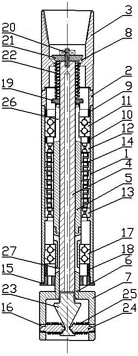
[0022] The hydraulic cutting device for deep-sea cutting casing includes a casing 1 , a connecting cylinder 2 , a joint 3 , a hollow shaft 4 , an upper sleeve 5 , a middle sleeve 6 and a lower sleeve 7 . A joint 3 is threadedly mounted on the top of the shell 1 through the connecting cylinder 2; the inner wall of the joint 3 is provided with a blocking hole 8, and the blocking hole 8 is a tapered hole. An upper sleeve 5 and a middle sleeve 6 are arranged inside the casing 1 below the flow blocking hole 8 , and the upper sleeve 5 and the middle sleeve 6 are threadedly connected. The upper sleeve 5 is equipped with an upper thrust bearing 11 through the spacer ring A9 and the spacer ring B10, and the upper sleeve 5 below the upper thrust bearing 11 is equipped with a turbine assembly 14 through a central bearing A12 and a central bearing B13. The turbine assembly 14 includes a rotor and stator.

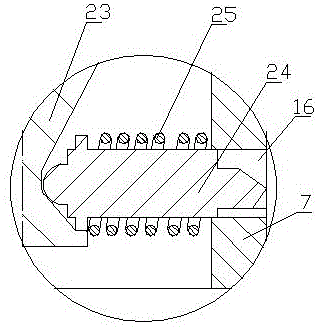
[0023] The lower port of the shell 1 is threaded with a shell end cap 15, the lower e


PUM


Abstract

The invention relates to a hydraulic cutting device for a deep sea cutting sleeve and belongs to technical field of repairing tools for natural gas pipes. The cutting device comprises a shell, a connecting drum, a joint, a hollow shaft, an upper sleeve, a middle sleeve and a lower sleeve, wherein the joint is screwed at the top end of the shell through the connecting drum; a flow baffle hole is formed in the joint; the upper sleeve and the middle sleeve are arranged in the shell under the flow baffle hole; the lower sleeve is arranged at the lower end of the middle sleeve; cutting holes are uniformly distributed on the periphery of the lower sleeve. The cutting device has a simple structure, is convenient in use and can solve the problems of the present tools that the structure is complex, the operation is complex, if the sleeve is fully cut cannot be confirmed, the cutting accident is easily caused and the cutting efficiency is low. The cutting device can be used for more effectively, quickly and safely cutting the deep sea sleeve and is especially suitable for cutting the deep sea cutting sleeve.

Description


Claims


Application Information

Patent Timeline
Owner YANGTZE UNIVERSITY
Why Eureka
Try Eureka