Bench and method for testing heat conductivity coefficient of heat exchange tube of EGR cooler

An EGR cooler and thermal conductivity technology, applied in the direction of material thermal development, etc., can solve the problems of destroying the heat exchanger tube, reducing the heat exchange efficiency of the cooler, and difficult to measure the thermal conductivity of the heat exchanger tube. Simple structure and strong practicability

Pending Publication Date: 2017-02-22
XIHUA UNIV
View PDF17 Cites 5 Cited by
  • Summary
  • Abstract
  • Description
  • Claims
  • Application Information

AI Technical Summary

Benefits of technology

This patented technology allows for accurate measurement of how well an object's temperature changes over time by measuring its ability to transfer energy efficiently through a material called a heat exchanger (HE). It does this while maintaining their original shape or function during operation.

Problems solved by technology

This technical problem addressed by this patented method relates to improving the performance or reducing emissions from engines that use exhaust gases recirculated with an intercooling system called Excavator®. Current methods involve measuring particle deposition onto surfaces inside the device's heat exchange section without damaging it during operation. However, there are challengings related to accurately monitoring how well these devices work at high speeds due to their small size.

Method used


Image

  • Bench and method for testing heat conductivity coefficient of heat exchange tube of EGR cooler
  • Bench and method for testing heat conductivity coefficient of heat exchange tube of EGR cooler
  • Bench and method for testing heat conductivity coefficient of heat exchange tube of EGR cooler

Examples


Embodiment Construction

[0024] The present invention will be further described below in conjunction with the accompanying drawings and specific embodiments.

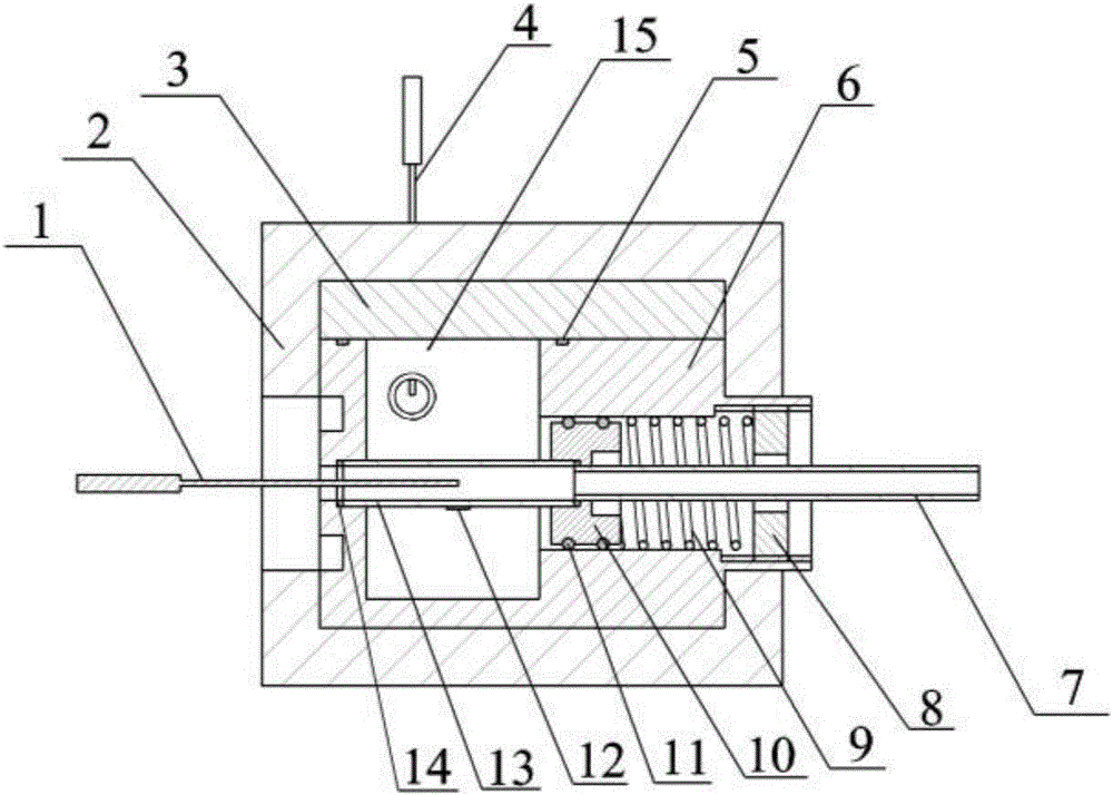
[0025] Such as figure 1 As shown, a test bench for thermal conductivity of heat exchange tubes of an EGR cooler includes a base body 6, a water storage chamber 15, a piston 10, and a spring fixing bolt 8; the base body 6 is an external sealing structure, and the inner left side is provided with a water storage chamber 15 , the right side is provided with a piston chamber and a spring fixing bolt 8 connected in sequence; the piston chamber is provided with a piston 10 and a spring 9, and the spring 9 is arranged on the right side of the piston 10; the spring 9 is connected to the spring fixing bolt 8 on the right side; the heat exchange tube 13 is set in the water storage chamber 15 of the base body 6, the air inlet end is externally connected to the base body 6, and the air outlet end is externally connected to the piston 10; the air outlet end of


PUM


Abstract

The invention discloses a test bench and method for testing the heat conductivity coefficient of the heat exchange tube of an EGR cooler. The test bench comprises a base body, a water storage chamber, a piston and a spring fixing bolt, wherein the base body is of an externally-sealed structure, the water storage chamber is arranged on the left in the base body, and a piston chamber and the spring fixing bolt which are sequentially connected are arranged on the right in the base body; the piston and a spring are arranged in the piston chamber, and the spring is arranged on the right of the piston; the spring is connected with the spring fixing bolt on the right of the spring; the heat exchange tube is arranged in the water storage chamber, the outside of the gas inlet end of the heat exchange tube is connected with the base body, and the outside of the gas outlet end of the heat exchange tube is connected with the piston; the gas outlet end of the heat exchange tube is connected with a hot air source outlet tube; a gas temperature sensor probe is arranged in the heat exchange tube, and a surface-mounted temperature sensor is arranged on the outer wall of the heat exchange tube; Each of the water inlet and the water outlet of the water storage chamber is provided with a temperature sensor. The test bench has the advantages that the heat conductivity coefficient of the heat exchange tube can be measured without destroying the heat exchange tube, the polluted heat exchange tube can also be measured, and the test bench is simple in structure, convenient to use and high in practicality.

Description


Claims


Application Information

Patent Timeline
Owner XIHUA UNIV
Why Eureka
Try Eureka