Boiler economizer

An economizer and boiler technology, applied in the field of boilers, can solve the problems of shortening the service life of boiler economizers, reducing the energy saving efficiency of boiler economizers, and easy dust accumulation of boiler economizers, so as to improve heat exchange efficiency, facilitate maintenance and replacement, Ease of cleaning

Active Publication Date: 2020-11-24
甘肃富士特暖通科技有限公司
View PDF16 Cites 1 Cited by
  • Summary
  • Abstract
  • Description
  • Claims
  • Application Information

AI Technical Summary

Benefits of technology

This new design for Boilers saves more fuel compared to previous designs while maintaining their effectiveness over longer periods of use. It includes two main technical features - one involves increasing the surface areas where there's direct connection between hot air flow and heat exchanger media (water) , another involving installing filters inside or outside the furnace itself instead of just relying solely upon them themselves. Additionally, it introduces a special mechanism called a coolness system that helps reduce excessive buildup of deposits during operation without requiring frequent replacements. Overall, this innovation enhances efficient performance and lifespan of the device.

Problems solved by technology

This patented technical problem addressed in this patents relates to improving the performance and durability of an economic unit called a furnace economizing agent (FEP). Biomass fuels have many advantages over traditional fossil sources such as low cost but also generate harmful emissions when burning them for producing power due to their small size compared with regular coals. These issues can lead to poor thermal exchange between the FEOX layer on top of the steel shell inside the furnace and the inner walls of the vessel's internal structure. To solve these challenges, various solutions are proposed including adding insulating materials like ceramic fiber wool layers or plastic foils to prevent excessive buildup of deposits caused by heavy metallurgies during operation.

Method used


Image

  • Boiler economizer
  • Boiler economizer
  • Boiler economizer

Examples


Embodiment Construction

[0023] In order to further illustrate the various embodiments, the present invention provides accompanying drawings, which are part of the disclosure of the present invention, and are mainly used to illustrate the embodiments, and can be used in conjunction with the relevant descriptions in the specification to explain the operating principles of the embodiments, for reference Those of ordinary skill in the art should be able to understand other possible implementations and advantages of the present invention. The components in the figures are not drawn to scale, and similar component symbols are generally used to represent similar components.

[0024] According to an embodiment of the present invention, a boiler economizer is provided.

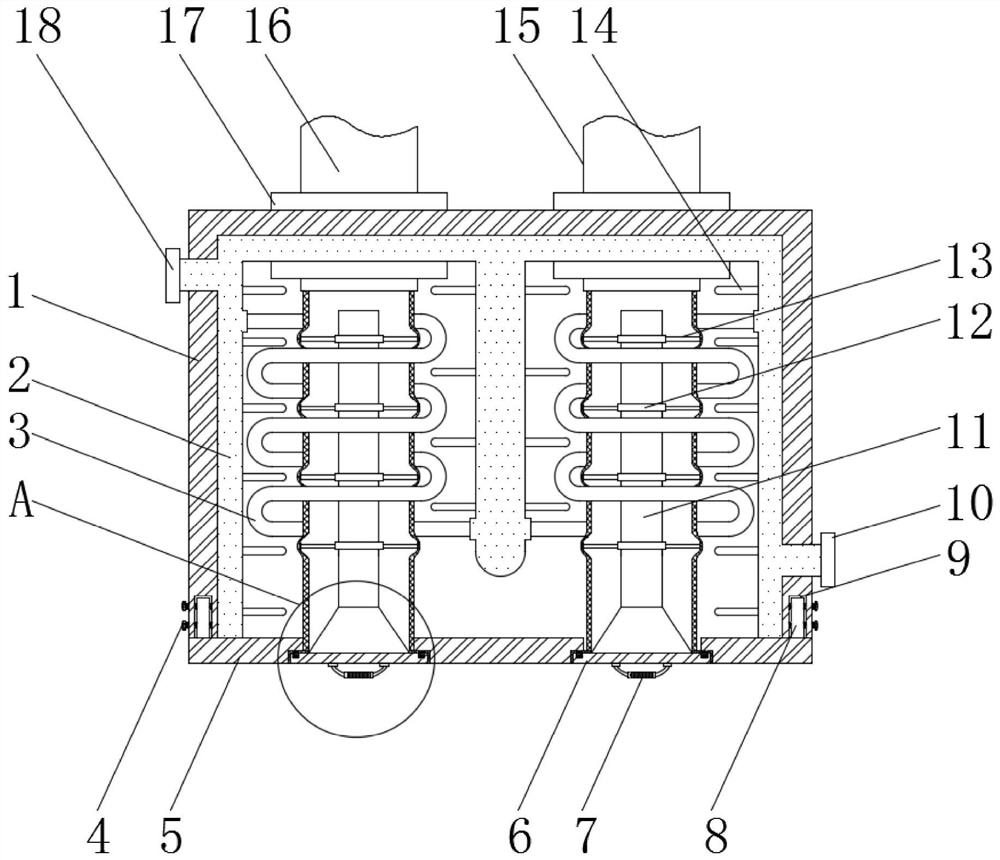
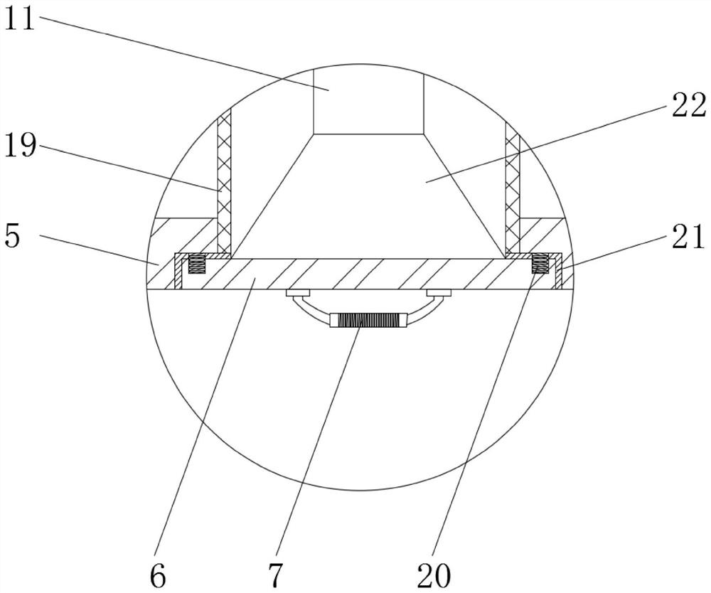
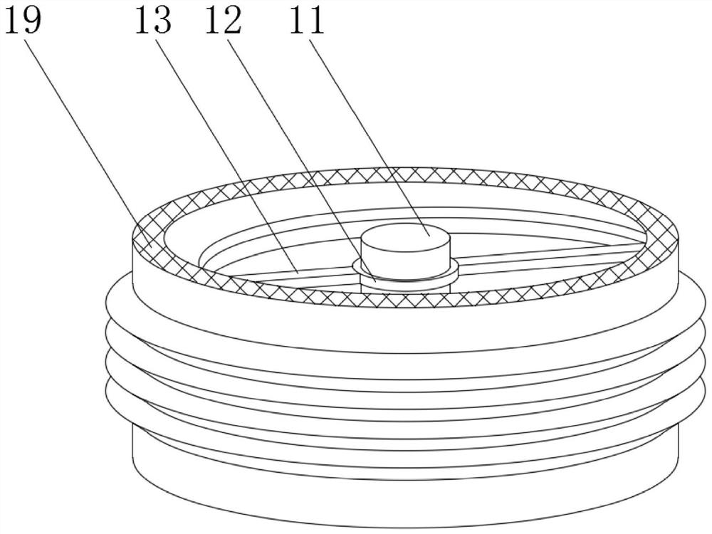
[0025] Now in conjunction with accompanying drawing and specific embodiment the present invention is further described, as Figure 1-3 As shown, a boiler economizer according to an embodiment of the present invention includes a thermal insulatio


PUM


Abstract

The invention discloses a boiler economizer comprising a thermal insulation shell and a water storage layer. One side of the top of the thermal insulation shell is connected with a smoke inlet, and the other side of the top of the thermal insulation shell is connected with a smoke outlet; high-temperature resistant filter bags are installed below the smoke inlet and the smoke outlet, and the side,close to the smoke inlet, of the water storage layer communicates with a cold water inlet; the other side of the water storage layer communicates with a hot water outlet, and the inner side of the water storage layer communicates with coiled pipes wound around the high temperature resistant filter bags; and a plurality of heat conduction fins are installed on the inner side of the water storage layer uniformly. The boiler economizer has the beneficial effects that the contact area between high temperature smoke and heat exchange media is increased, so that the heat exchange efficiency of equipment is improved; the energy-saving efficiency is high, and meanwhile the high-temperature resistant filter bags are arranged, and can be used for filtering the high temperature smoke in the boiler economizer; an ash clearing mechanism is arranged, so that massive accumulation of ash in the boiler economizer is reduced effectively; the heat exchange efficiency is ensured, and the energy-saving efficiency is further improved; and the service life of the equipment is further prolonged.

Description


Claims


Application Information

Patent Timeline
Owner 甘肃富士特暖通科技有限公司
Why Eureka
Try Eureka