Motorcycle oil tank

A technology for motorcycles and fuel tanks, applied in gasoline drums, vehicle parts, bicycle accessories, etc., can solve the problems of low fuel tank assembly efficiency, increase the risk of oil leakage from the fuel tank body, tedious and time-consuming assembly, and reduce false alarms. , Reduce the risk of oil leakage, the effect of simple and convenient assembly

Inactive Publication Date: 2017-03-15
重庆特巴斯科技有限公司
View PDF0 Cites 2 Cited by
  • Summary
  • Abstract
  • Description
  • Claims
  • Application Information

AI Technical Summary

Problems solved by technology

In order to realize the installation of the oil switch and the oil level sensing device, it is often necessary to provide two installation holes corresponding to the oil switch and the oil level sensing device on the fuel tank body, the

Method used


Image

  • Motorcycle oil tank
  • Motorcycle oil tank
  • Motorcycle oil tank

Examples


Embodiment Construction

[0015] In the following, the present invention will be further described in conjunction with the accompanying drawings and specific embodiments, so as to understand the technical ideas claimed in the present invention more clearly.

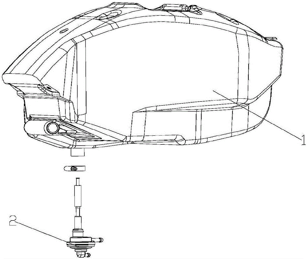
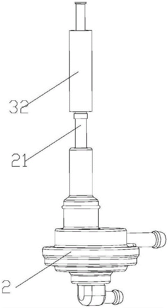
[0016] Such as figure 1 , 2 , shown in 3, is a kind of motorcycle fuel tank of the present invention, comprises fuel tank body 1, is installed in the negative pressure diaphragm type oil switch 2 at the installation hole place of fuel tank body 1 lower end, oil level sensing device, alarm circuit; The top of the negative pressure diaphragm oil switch 2 is also provided with a top pipe 21 located in the fuel tank body 1; the oil level sensing device includes a reed switch and a float 32; the reed switch is constituted as a switch on the alarm circuit, Used to control the on-off of the alarm circuit; the reed switch is installed in the top pipe 21, and the float 32 is movably fitted on the top pipe 21 and can rise and fall with the liquid level of the


PUM


Abstract

The invention relates to a motorcycle oil tank. The motorcycle oil tank comprises an oil tank body, a negative-pressure diaphragm type oil switch which is mounted at a mounting hole formed in the lower end of the oil tank body, an oil level induction device and an alarming circuit, wherein an ejection pipe, which is located in the oil tank body, is further arranged at the top of the negative-pressure diaphragm type oil switch; the oil level induction device comprises a reed switch and a floater; the reed switch forms a switch on the alarming circuit and is used for controlling switching-on/off of the alarming circuit; the reed switch is mounted in the ejection pipe, and the ejection pipe is a copper pipe; the floater movably sleeves the ejection pipe and can be hoisted along the liquid level of the oil tank body; the floater is further provided with a magnetic ring; and the magnetic ring can move along the floater and is used for controlling switching-on or switching-off of the reed switch. The invention aims at providing the motorcycle oil tank, a structure of the oil level induction device is reasonably set and an assembling position of the oil level induction device is reasonably set, so that the oil leakage risk of the oil tank body can be reduced and the assembling efficiency of the whole oil tank can be improved.

Description


Claims


Application Information

Patent Timeline
Owner 重庆特巴斯科技有限公司
Why Eureka
Try Eureka