Pipe conveying device and switching valve thereof

A switching valve and pipeline technology, applied in the field of switching valves and pipeline conveying devices, can solve problems such as large pipeline resistance, large pipeline curvature, and thick material ejection, and achieve long-term high-efficiency on-off switching and small impact effects.

Inactive Publication Date: 2017-06-16
FENY
View PDF6 Cites 2 Cited by
  • Summary
  • Abstract
  • Description
  • Claims
  • Application Information

AI Technical Summary

Problems solved by technology

However, when the inlet and outlet of the concentrated material are connected with the groove 5, the pipeline curvature is too large, the resistance of the pipeline is large, the energy loss is high, and the concentrated material is easy to be ejected from between the valve core 2 and the valve body 1; in this

Method used


Image

  • Pipe conveying device and switching valve thereof
  • Pipe conveying device and switching valve thereof
  • Pipe conveying device and switching valve thereof

Examples


Embodiment Construction

[0022] The core of the present invention is to provide a switching valve, which can efficiently realize the on-off switching of multiple pipelines for a long time. Another core of the present invention is to provide a pipeline conveying device including the above-mentioned switching valve, so that it can realize the on-off switching of multiple pipelines in a long-term and efficient manner.

[0023] In order to enable those skilled in the art to better understand the solution of the present invention, the present invention will be further described in detail below in conjunction with the accompanying drawings and specific embodiments.

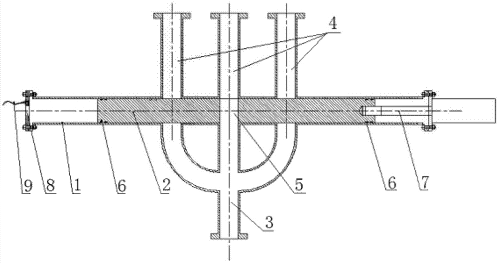
[0024] Please refer to image 3 , image 3 It is a structural schematic diagram of a specific embodiment of the switching valve provided by the present invention.

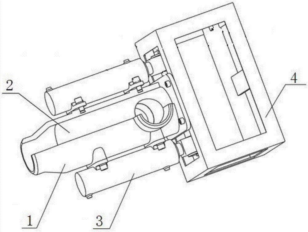
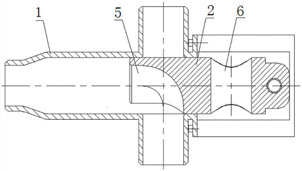
[0025] The switching valve provided by the specific embodiment of the present invention includes a tubular valve body 1 and a valve core 2 which is arranged inside the valve body 1 a


PUM


Abstract

The invention discloses a switching valve which comprises a valve body, a valve core, a driving device and a main pipe. A plurality of branch pipes which are communicated and sequentially arranged on one side of the outer wall of the valve body are communicated with the tail end of the main pipe. A plurality of output pipes are communicated with the other side of the outer wall of the valve body. Through holes for communicating the corresponding branch pipes with the output pipes are formed in the valve core. When the valve core slides to the set position inside the valve body, one branch pipe on one side of the outer wall of the valve body is communicated with the corresponding output pipe on the other side of the outer wall of the valve body through the corresponding through hole; the number of the output pipes of the switching valve is adjustable, no large turning angle exists in the switching process, the switching resistance and impact on the valve core are small, and therefore the switching valve can achieve on-off switching of the pipes in a long-term and efficient mode. The invention further discloses a pipe conveying device comprising the switching valve.

Description


Claims


Application Information

Patent Timeline
Owner FENY
Why Eureka
Try Eureka