Relay protection device in transmission line

A relay protection device and transmission line technology, which is applied in the direction of emergency protection circuit devices, measuring devices, measuring electricity, etc., can solve problems such as abnormal differential current, slow communication speed, man-made damage caused by climate damage, and the influence of self-stability and reliability. Achieve high security, protect security and stability, and facilitate extensibility

Inactive Publication Date: 2017-06-20
赵志国
View PDF5 Cites 0 Cited by
  • Summary
  • Abstract
  • Description
  • Claims
  • Application Information

AI Technical Summary

Benefits of technology

This new system uses wireless signals from satellites or ground stations to monitor and control power distribution systems at remote locations along their length. It includes features like monitoring devices that are easy to install and test over longer periods without requiring physical connections between them and controlling these components remotively. These improvements make communication networks safer, less prone to damage caused by external factors such as weather conditions or other natural disasters.

Problems solved by technology

This patented describes different technical problem addressed during this patents' development: how to protect transmission lines from environmental factors like temperature stress that can cause failure while transmitting signals over them; how to ensure proper operation even if one side fails without shutting down all others connected together with redundant components such as relays.

Method used


Image

  • Relay protection device in transmission line
  • Relay protection device in transmission line
  • Relay protection device in transmission line

Examples


Embodiment Construction

[0014] Below in conjunction with accompanying drawing and specific embodiment the present invention is described in further detail:

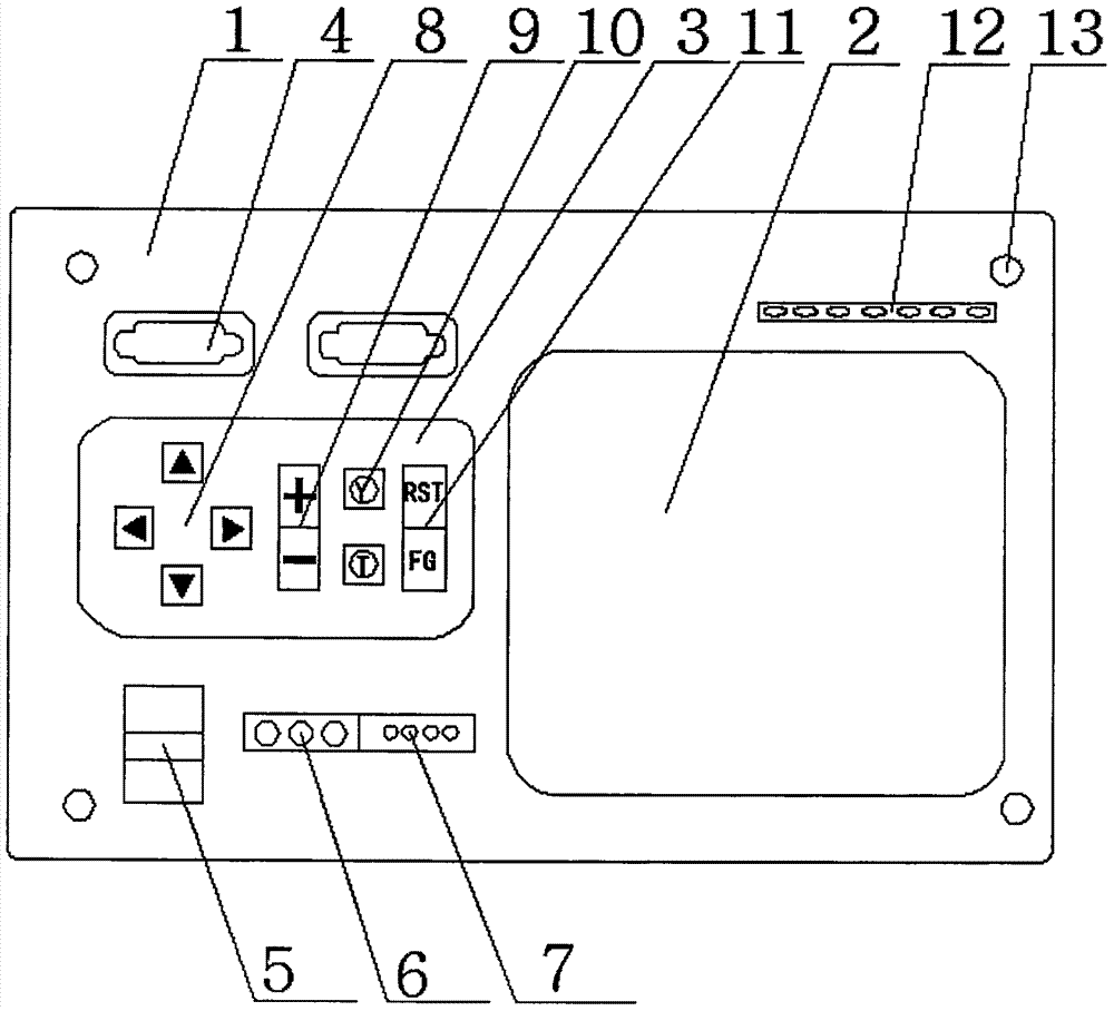
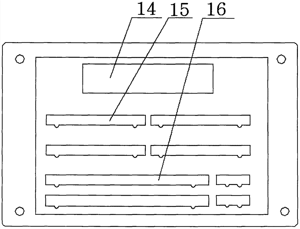
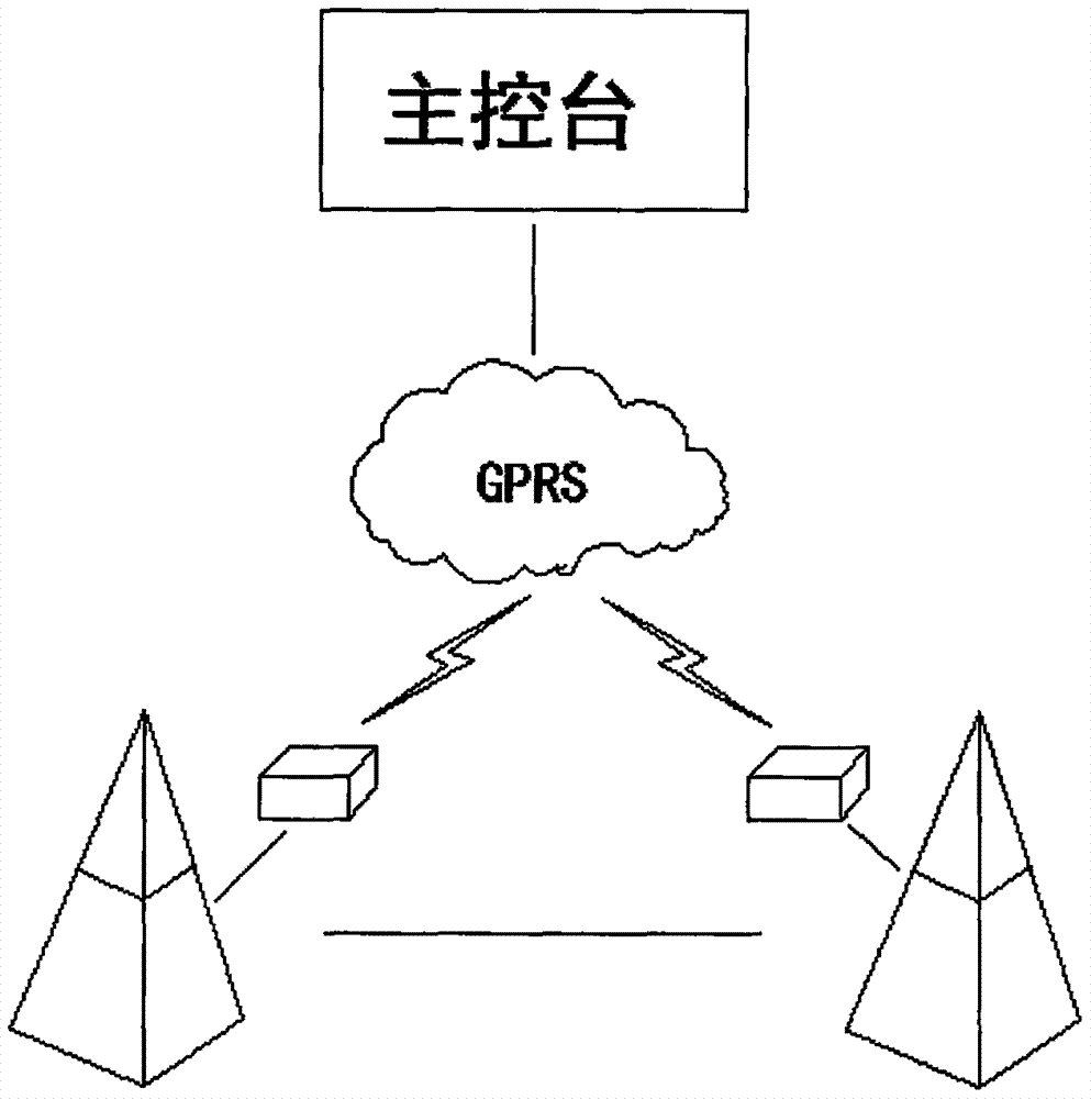
[0015] Such as figure 1 , figure 2 , image 3 As shown, a relay protection device in a power transmission line includes a box body (1), an LED display screen (2), a function key group (3), a maintenance interface (4) and a detection connection hole; the box body ( 1) An LED display (2) is provided on the right side of the front; an indicator light (12) is provided on the LED display (2); and a plurality of maintenance interfaces (4) are provided on the upper left side of the front of the box (1) The lower end of the maintenance interface (4) is provided with the function key group (3); the lower end of the function key group (3) is provided with a relay switch (5) and the detection connection hole; the box body (1 ) front four corners are all fixed by screws (13); the function key group (3) is direction key (8), confirmation key (10), cancel ke


PUM


Abstract

The invention discloses a relay protection device in a transmission line. The relay protection device comprises a box body, an LED display screen, a function key group, a maintenance interface and a detection hole. The LED display screen is arranged on the right side of the front of the box body. An indication lamp is arranged on the LED display screen. A number of maintenance interfaces are arranged on the upper end of the left side of the front side of the box body. The function key group is arranged below the maintenance interfaces. A relay switch and the detection hole are arranged below the function key group. Four corners of the front side of the box body are fixed by screws. According to the invention, the protection demand of the transmission line is met; the relay protection device can be arranged in a transmission tower for a long time, processes detected data through the GPS network, sends the data to a console, and can carry out on-site maintenance and detection; a front plugboard member facilitates the ductility of each board of the device; and the device has the advantages of high safety, stability and reliability.

Description


Claims


Application Information

Patent Timeline
Owner 赵志国
Why Eureka
Try Eureka