Glass fiber forming area cooling air bellow
A technology for cooling bellows and glass fiber, which is applied in the direction of pipeline layout, etc., can solve the problems of easy production of wool yarn and unstable quality of raw silk products, and achieve the effects of avoiding energy waste, improving effective utilization rate, and reducing ambient temperature
- Summary
- Abstract
- Description
- Claims
- Application Information
AI Technical Summary
Problems solved by technology
Method used
Image

Examples
Embodiment 1
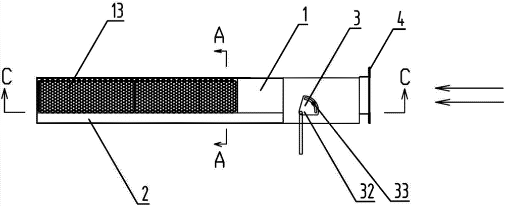
[0033] like figure 2 and image 3 As shown, it is a front view of an embodiment of a glass fiber forming zone cooling air box of the present invention. The direction indicated by the arrow in the figure is a schematic direction of the flow direction of the cooling air.
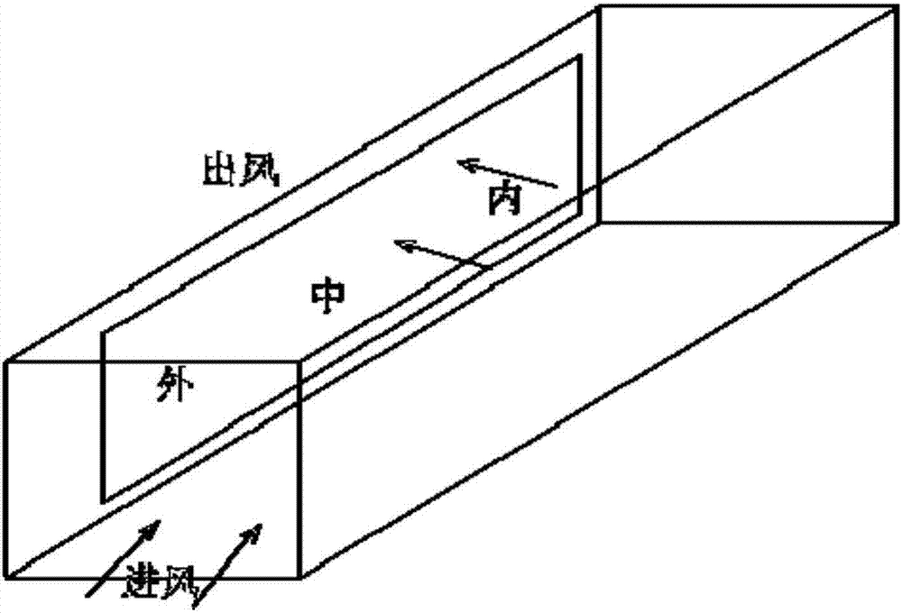
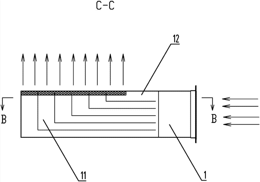
[0034] A cooling bellows in a glass fiber molding area, comprising a molding bellows 1 and a plurality of air ducts arranged in the molding bellows 1; the air inlet and the air outlet of the molding bellows 1 are perpendicular to each other; They are separated by L-shaped plate-shaped members; the air inlets of the plurality of air ducts are all arranged at the air inlets of the forming bellows 1 and equally divide the air surface at the air inlets of the forming bellows 1 from the area. The air outlets of each of the air ducts are arranged at the air outlets of the forming bellows 1 and equally divide the air surface at the air outlets of the forming bellows 1 from the area. The cooling air box in the glass
Embodiment 2
[0043] The difference from Example 1 is that, as Figure 2-7 As shown in the figure, the direction indicated by the arrow in the figure is the flow direction of the cooling air. The cooling bellows in the glass fiber forming area also includes a damper 3 and an air-conditioning bellows 2. The air-conditioning bellows 2 is placed below the molding bellows 1. The air inlet of the air-conditioning bellows 2 is communicated with the air inlet of the molding bellows 1, and the air valve 3 can control the cooling air to enter the air-conditioning bellows 2 or the molding bellows 1 or can adjust the air inlet of the air-conditioning bellows 2 and the air-conditioning bellows 2. The size of the air inlet of the molding bellows 1. By setting the air valve 3 at the air inlet inside the bellows, the dual-purpose function of the bellows is realized, that is, when the raw silk production is in normal operation, the air valve 3 is adjusted to the cooling tow mode, and the cooling air flows to
PUM
| Property | Measurement | Unit |
|---|---|---|
| Slope | aaaaa | aaaaa |
Abstract
Description
Claims
Application Information
 - R&D Engineer
- R&D Manager
- IP Professional
- Industry Leading Data Capabilities
- Powerful AI technology
- Patent DNA Extraction
Browse by: Latest US Patents, China's latest patents, Technical Efficacy Thesaurus, Application Domain, Technology Topic.
© 2024 PatSnap. All rights reserved.Legal|Privacy policy|Modern Slavery Act Transparency Statement|Sitemap