Air filter cleaning device

An air filter and cleaning device technology, which is applied in air conditioning systems, space heating and ventilation, heating methods, etc., can solve the problem that manual cleaning is not clean enough, in place, the filter does not have ash removal function, and the filtering effect of the filter becomes poor and other problems, to achieve the effect of simple structure, convenient dust collection, and improved work efficiency

Active Publication Date: 2017-07-25
东莞市万恩环保科技有限公司
View PDF5 Cites 3 Cited by
  • Summary
  • Abstract
  • Description
  • Claims
  • Application Information

AI Technical Summary

Benefits of technology

This patented technology allows for efficient automated movement by controlling both the position of the moving parts (push or pull) and their movements through various ways such as rotating wheels that move along rails or guides. It also includes features like automatically closing doors when there's no motion being done during this process, improving security while collecting debris from inside walls without causing damage due to external impact force. Additionally, it provides easy accessibility for maintenance purposes. Overall, these technical improvements enhance the performance and ease at which they operate.

Problems solved by technology

This patented technical problem addressed by this patents relates to improving the efficiency with which indoor spaces are filtered due to their high concentration of harmful gases such as formaldehyde (formal) gas or volatile organic compounds (VOC). Current methods involve removing these substances from an interior space through regular maintenance work without effective ways to remove any particles on its surface. Additionally, existing solutions require frequent manual cleanings overtime, making them difficult to maintain effectively.

Method used


Image

  • Air filter cleaning device
  • Air filter cleaning device
  • Air filter cleaning device

Examples


Embodiment Construction

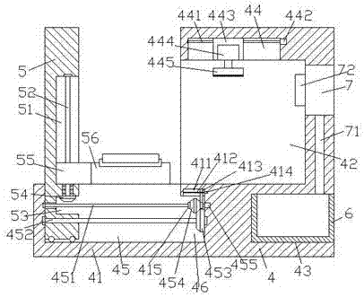
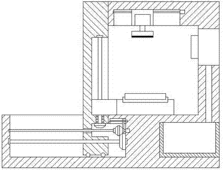
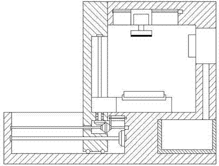
[0024] like Figure 1-Figure 7 As shown, an air filter cleaning device of the present invention includes a base frame 4 provided with a pushing part 41 on the left side, and a cleaning chamber 42 is provided in the left end surface of the base frame 4 on the upper side of the pushing part 41, A first chute 44 is provided on the inner top surface of the cleaning chamber 42, and a first screw rod 441 is arranged in the first chute 44, and a cleaning slide is connected with a screw fit on the first screw rod 441. Block 443, the push part 41 is provided with a second chute 45 extending left and right, and the base frame 4 on the right side of the push part 41 is provided with an embedded groove 46, and the embedded groove 46 The left end communicates with the extended tail on the right side of the second chute 45, and a second screw rod 452 is provided between the right inner wall of the embedded groove 46 and the left inner wall of the second chute 45, A spline column 451 is provid


PUM


Abstract

The invention discloses an air filter cleaning device. The device comprises a base frame with a pushing part on the left side, a cleaning cavity is formed in the position, on the upper side of the pushing part, in the left side end face of the base frame, a first sliding groove is formed in the inner top face of the cleaning cavity, a first screw rod is arranged in the first sliding groove, a cleaning sliding block is in fit connection with the first screw rod in a screw manner, a second sliding groove is arranged in the pushing part in a left-and-right extension manner, an embedding groove is formed in the position, on the right side of the pushing part, in the base frame, the left side end of the embedding groove and the extension tail end of the right side of the second sliding groove are arranged in a communication and penetration manner, a second screw rod is arranged between the inner wall of the right side of the embedding groove and the inner wall of the left side of the second sliding groove, a spline column is arranged at the position, above the second screw rod, of the inner wall of the right side of the embedding groove and the left side inner wall of the second sliding groove, a first conical wheel is fixedly connected to the second screw rod in the embedded groove, and a pushing sliding block which extends upwards is in fit connection with the second screw rod in the second sliding groove in a screw manner. The device is simple in structure, convenient to operate, high in safety, high in work efficiency and capable of reducing labor intensity.

Description


Claims


Application Information

Patent Timeline
Owner 东莞市万恩环保科技有限公司
Why Eureka
Try Eureka