Low earth orbit satellite smart antenna receiving system and method

A technology of a smart antenna and a receiving system, applied in the field of satellite communications, can solve the problems of difficult handover management, weak on-orbit autonomous reconstruction capability of multi-beam patterns, etc., and achieve the effects of high gain and strong airspace adaptive interference suppression capability.

Active Publication Date: 2017-08-18
NANJING UNIV OF SCI & TECH +1
View PDF6 Cites 23 Cited by
  • Summary
  • Abstract
  • Description
  • Claims
  • Application Information

AI Technical Summary

Problems solved by technology

The ground-covering multi-beam receiving antennas of these systems have the following problems: (1) The ability to autonomously reconstruct the multi-beam patterns o

Method used


Image

  • Low earth orbit satellite smart antenna receiving system and method
  • Low earth orbit satellite smart antenna receiving system and method
  • Low earth orbit satellite smart antenna receiving system and method

Examples


Embodiment

[0057] Aiming at the low-orbit satellite communication system / load of a limited number of simultaneous burst users, the present invention provides an uplink for the space-borne spread spectrum communication system, which adopts zero trap anti-jamming digital multi-beam forming technology and multi-target angle estimation technology, simultaneously form the acquisition multi-beam and high-gain tracking multi-beam with equal flux to the ground, and automatically adjust the pointing angle of the tracking beam and the adaptive resistance of the low-orbit communication system / load of the acquisition and tracking beam pattern null position. Interfering with multi-beam smart antenna receiving systems.

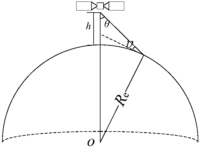
[0058] The orbit height of low-orbit communication satellites is generally between 750km and 1800km. The installation position of the smart antenna using digital beamforming technology is facing the earth, and the geometric relationship between the satellite and the earth is shown in


PUM


Abstract

The invention relates to a low earth orbit satellite smart antenna receiving system and method. The receiving system is composed of an array antenna consisting of N element antennas, N paths of digital receivers and a self-adaptive anti-interference smart antenna digital circuit; the smart antenna receiving system adopts a nulling anti-interference digital multi-beam forming technology and a multi-objective angle estimation technology, which can form a capture beam and a tracking beam at the same time; the tracking beam pointing is adjusted in real time according to a user angle estimation result or satellite orbit characteristics; and the interference nulling positions of the capture and tracking beams are adjusted in real time according to an interference angle estimation result or the satellite orbit characteristics. The low earth orbit satellite smart antenna receiving system provided by the invention can quickly locate the interference and the target, and form a nulling direction pattern in the airspace to suppress the interference of dynamic changes, so that the low earth orbit satellite smart antenna receiving system is especially suitable for a smart antenna system for low earth orbit satellite earth communication.

Description


Claims


Application Information

Patent Timeline
Owner NANJING UNIV OF SCI & TECH
Why Eureka
Try Eureka