Latching implement

A pendant and component technology, applied in the field of card pendants, can solve the problems of troublesome disassembly, poor disassembly operability, etc.

Active Publication Date: 2017-10-13
SUGATSUNE IND CO LTD
View PDF7 Cites 1 Cited by
  • Summary
  • Abstract
  • Description
  • Claims
  • Application Information

AI Technical Summary

Problems solved by technology

[0004] However, in the past, when this kind of hanging piece was to be released from the hanging portion (hanging hole) of the supporting body such as the box frame column, it was necessary to pull up the anti-pull part and

Method used


Image

  • Latching implement
  • Latching implement
  • Latching implement

Examples


Embodiment Construction

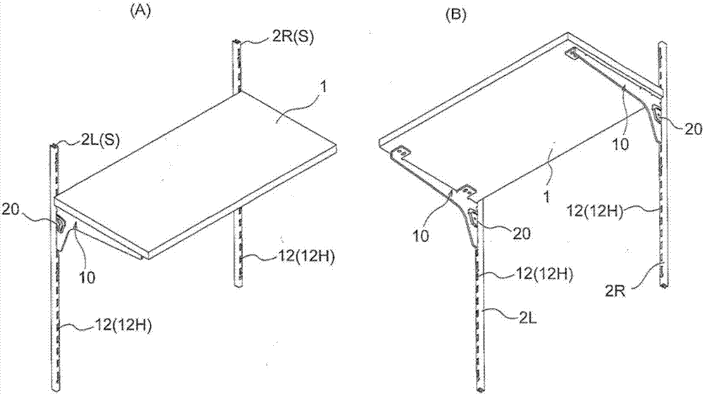
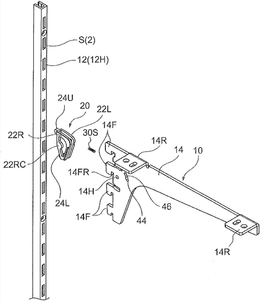
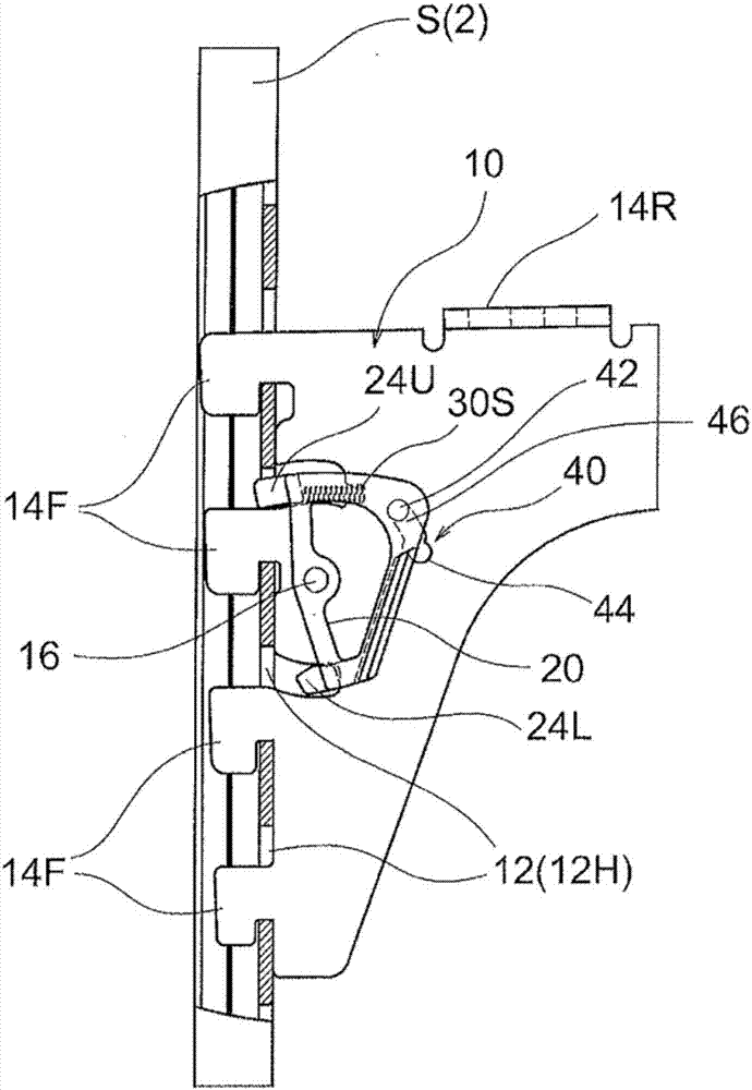
[0071] Embodiments of the present invention will be described in detail with reference to the accompanying drawings. Hanger 10 of the present invention, as an example, as figure 1 As shown, it is also used as a box frame bracket for supporting the box frame plate 1 and clamped on a pair of box frame columns 2R, 2L (hereinafter collectively referred to as label 2), but in addition to being used as the box frame bracket, the present invention Card pendant 10 is also applicable to such as Figure 17 The clothes-hanging support tube holder supporting horizontal clothes-hanging support tube 3 as shown or as Figure 18 The shown clothes hanger supports the vertical clothes hanger support tube 4 with a plurality of clothes hanger hooks. In addition, the support S held by the hanger 10, in addition to figure 1 , Figure 17 , Figure 18 In addition to the box frame columns shown, it can also be, for example, the side wall of a metal cabinet with 1 or more clamping holes.

[0072] Han


PUM


Abstract

A lifting prevention member 20 pivots on a latching implement main body 14 having hooks 14F which latch into latching holes 12H in a shelf post 2, in such a way as to move between a position preventing the latching implement main body 14 from being lifted, and a position permitting the latching implement main body 14 to be lifted. A temporary holding protuberance 42 which engages with a temporary holding recessed portion 44 in the latching implement main body 14 when the lifting prevention member 20 is in the position permitting lifting is provided in the lifting prevention member 20. By this means, the latching implement main body is temporarily held and retained in the position permitting lifting, from the position preventing lifting, when the latching implement main body is to be removed from the shelf post, and therefore the latching implement main body can be removed easily from the shelf post.

Description


Claims


Application Information

Patent Timeline
Owner SUGATSUNE IND CO LTD
Why Eureka
Try Eureka