Water tank and heat pump water heater provided with same

A water tank and heat pump technology, which is applied to fluid heaters, lighting and heating equipment, etc., can solve the problems of unsatisfactory descaling effect of water tanks, and achieve the effect of improving sewage discharge effect, increasing hot water output rate, and enhancing water flow disturbance.

Inactive Publication Date: 2017-10-31
QINGDAO HAIER NEW ENERGY ELECTRIC APPLIANCE
View PDF8 Cites 0 Cited by
  • Summary
  • Abstract
  • Description
  • Claims
  • Application Information

AI Technical Summary

Problems solved by technology

[0003] The purpose of the first aspect of the present invention is to overcome the defect that the descaling effect of the existing water tank is not ideal, and to provide a nov

Method used


Image

  • Water tank and heat pump water heater provided with same
  • Water tank and heat pump water heater provided with same

Examples


Embodiment Construction

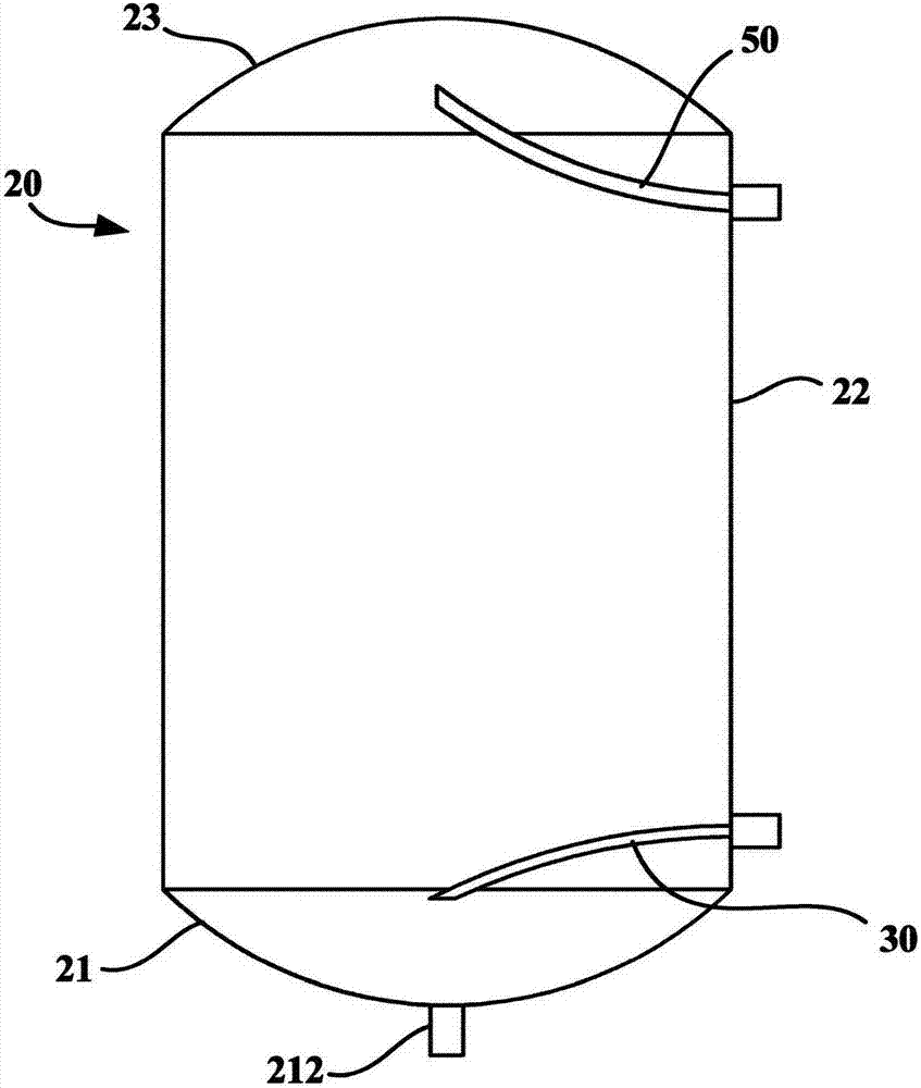
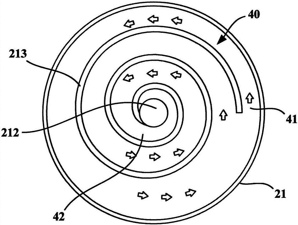
[0022] figure 1 is a schematic structural diagram of a water tank according to an embodiment of the present invention, figure 2 is a schematic top view of the sewage channel 40 in the water tank according to one embodiment of the present invention. Such as figure 1 with figure 2 As shown, the embodiment of the present invention provides a water tank, which at least includes a tank body 20 and a water inlet pipe 30 . The box body 20 may have a bottom wall 21 and a peripheral wall 22 extending upward from a peripheral edge of the bottom wall 21 . Further, the box body 20 may also have a top wall 23 disposed on the upper end of the peripheral wall 22 . The water tank in this embodiment can also have a water outlet pipe 50 .

[0023] Particularly, in the water tank of this embodiment, the inner surface of the bottom wall 21 protrudes upwards out of the ribs 213 or is recessed downwards to form a groove, so as to define the place where the outlet end 42 is located at the lowest


PUM

PropertyMeasurementUnit
Depthaaaaaaaaaa

Abstract

The invention relates to a water tank and a heat pump water heater provided with the same. Specifically, the water tank provided by the invention comprises a tank body and a water inlet pipe. The tank body is provided with a bottom wall and a circumferential wall formed by stretching upward from the circumference of the bottom wall. The inner surface of the bottom wall protrudes upwards to form a rib or is recessed downwards to form a groove, so that a sewage discharge channel with the outlet end being located in the lowest position of the inner surface of the bottom wall is defined. The water inlet pipe is configured to be capable of conveying water to the inlet end of the sewage discharge channel, so that the flow direction of at least part of water is changed by the sewage discharge channel, and at least dirt in the zone, covered by the sewage discharge channel, of the inner surface of the bottom wall is taken to the lowest position of the inner surface of the bottom wall. In addition, the invention further provides the heat pump water heater provided with the water tank. According to the water tank, flow disturbance during sewage discharge can be improved, so that the bottom dirt of the water tank is removed more easily, and the sewage discharge effect is improved.

Description


Claims


Application Information

Patent Timeline
Owner QINGDAO HAIER NEW ENERGY ELECTRIC APPLIANCE
Why Eureka
Try Eureka