Heating water heater for boiler

A heating water and heater technology, applied in water heaters, fluid heaters, lighting and heating equipment, etc., can solve the problem that heating water cannot be fully heated, and achieve stable heating effect

Inactive Publication Date: 2018-01-23
金仁洙 +1
View PDF5 Cites 0 Cited by
  • Summary
  • Abstract
  • Description
  • Claims
  • Application Information

AI Technical Summary

Benefits of technology

This technology allows for more efficient use of electrical energy compared with traditional methods like burning fuel or resistance wire-wound type power supply systems. It achieves this by utilizing two rows of square pyrolytic carbon (PCM)-based heaters inside one channel on both sides of each other at right angles. These PCMs create a zigsaw pattern where they connect together into different parts called channels. By placing these components correctly within certain specific areas around them, it becomes possible to achieve even greater efficiency than previous designs without adding extra materials such as wires or insulators.

Problems solved by technology

Inventional methods described in these technical problem addressed in the patents include slow down moving fluid from an upstream end towards another area where it can get too warm compared to what was initially located within them.

Method used


Image

  • Heating water heater for boiler
  • Heating water heater for boiler
  • Heating water heater for boiler

Examples


Embodiment Construction

[0046] Hereinafter, configurations of specific embodiments of the present invention will be described with reference to the accompanying drawings.

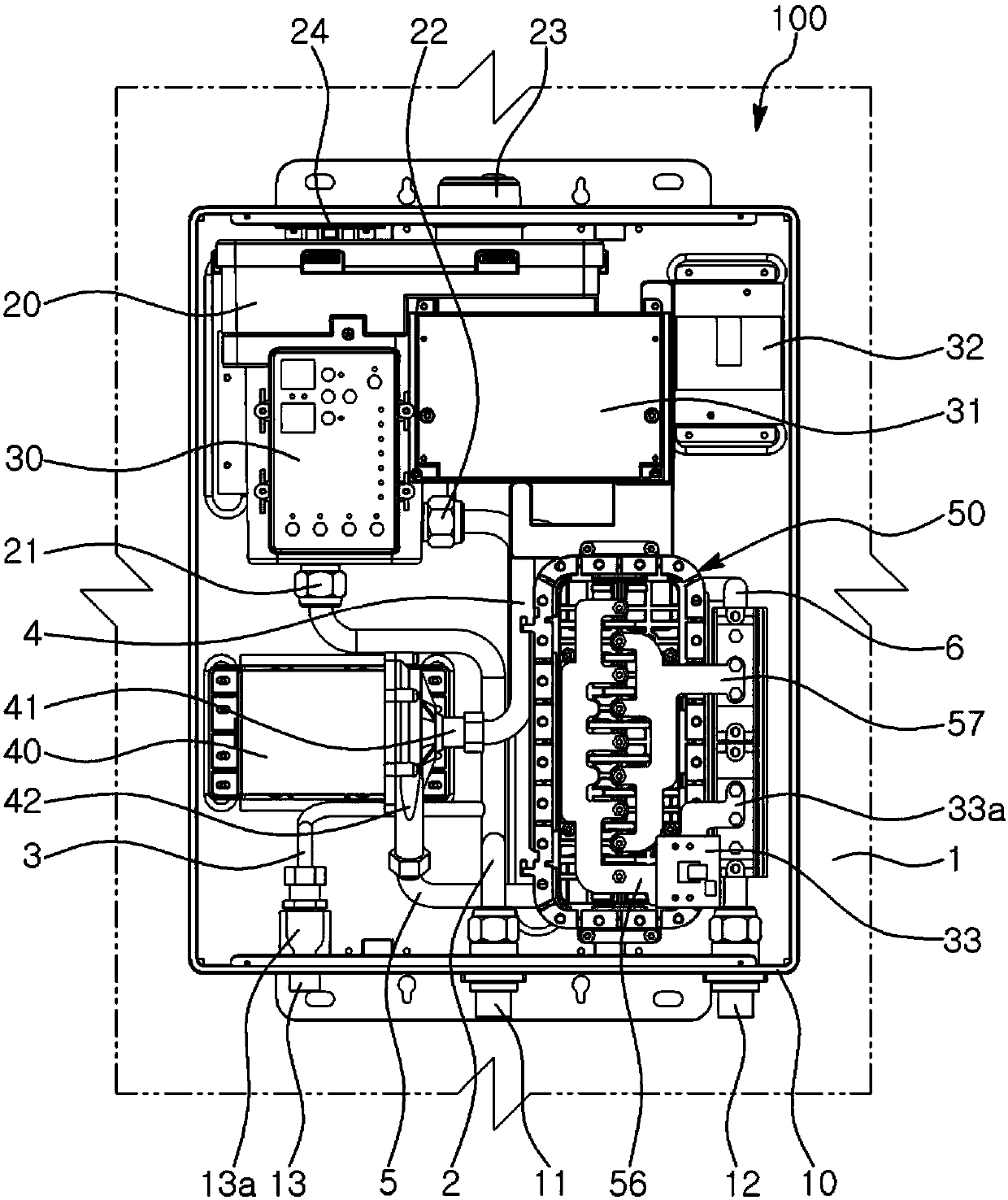
[0047] Such as Figure 1 to Figure 8 As shown, the boiler 100 provided with the heating water heater 50 according to the embodiment of the present invention is arranged on the wall 1 in the shape of a square barrel, including the boiler box 10 . The boiler box has: a first heating water inlet 11 provided on the lower surface of the outside, through which heating water circulated for heating flows in; and a first heating water outlet 12 through which the heating water is discharged.

[0048] In addition, the boiler 100 is provided with a water tank 20 on the upper side inside the boiler box 10 . The water tank 20 has a second heating water inlet 21 connected to the first heating water inlet 11 via the first moving pipe 2 , and a second heating water outlet 22 .

[0049] Here, the water tank 20 is provided with a cover 23 exposed to


PUM


Abstract

A heating water heater for boiler disclosed by the invention is characterized in that the heater includes a plurality of quadrangle graphite heating elements disposed in a shell and a shield bonded tothe shell, and provided with electrode rods connected to the controller through an anode and a cathode alternatively respectively. One side of the shell and one side of the shield are opened to formfirst and second internal spaces. To ensure insertion of the plurality of quadrangle graphite heating elements, first and second inserting ends are disposed inside side surfaces of the first and second internal spaces. To ensure movement of heating water towards the first and second internal spaces among the inserted quadrangle graphite heating elements, first and second guide slots wider than thequadrangle graphite heating elements are arranged in a zigzag manner along the length direction in the opposite first and second internal spaces. A fourth heating water inlet and a fourth heating water outlet which are communicated with the first internal space are arranged at two ends of the shell respectively. The heating water is guided along the first and second guide slots and in the first and second internal spaces among the quadrangle graphite heating elements.

Description


Claims


Application Information

Patent Timeline
Owner 金仁洙
Why Eureka
Try Eureka