Plate glue spreading device

A technology for sheet materials and gluing rollers, which is applied to surface coating liquid devices, surface pretreatment, chemical instruments and methods, etc., which can solve problems such as uneven gluing, increased workload of staff, and inconvenient gluing work. , to achieve the effect of accelerating the air flow speed, accelerating the solidification rate and improving work efficiency

Inactive Publication Date: 2017-11-24
LIANGXI HAOXING IND DESIGN OFFICE
View PDF0 Cites 15 Cited by
  • Summary
  • Abstract
  • Description
  • Claims
  • Application Information

AI Technical Summary

Problems solved by technology

Usually, the glue is applied manually to the surface of the board. Manual glue brushing will not only increase the workload of the staff, but also cause uneven glue brushing. Due to the limitation of the working environment, most of the glue used for brushing is hot-melt glue. The existing gluing device adopts the method of dripping

Method used


Image

  • Plate glue spreading device
  • Plate glue spreading device

Examples


Embodiment Construction

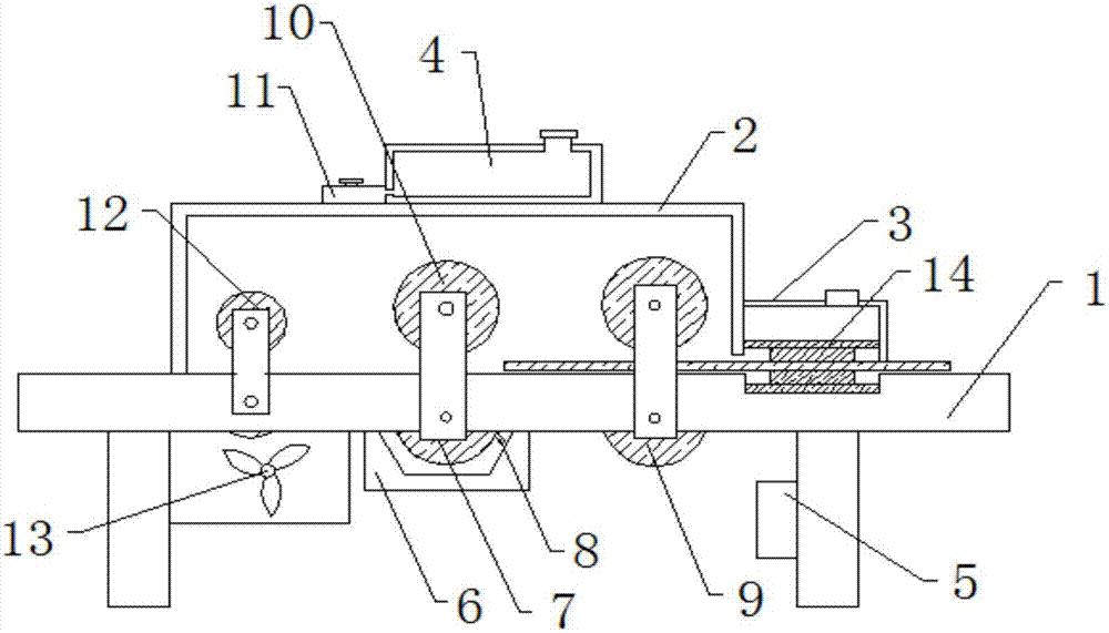
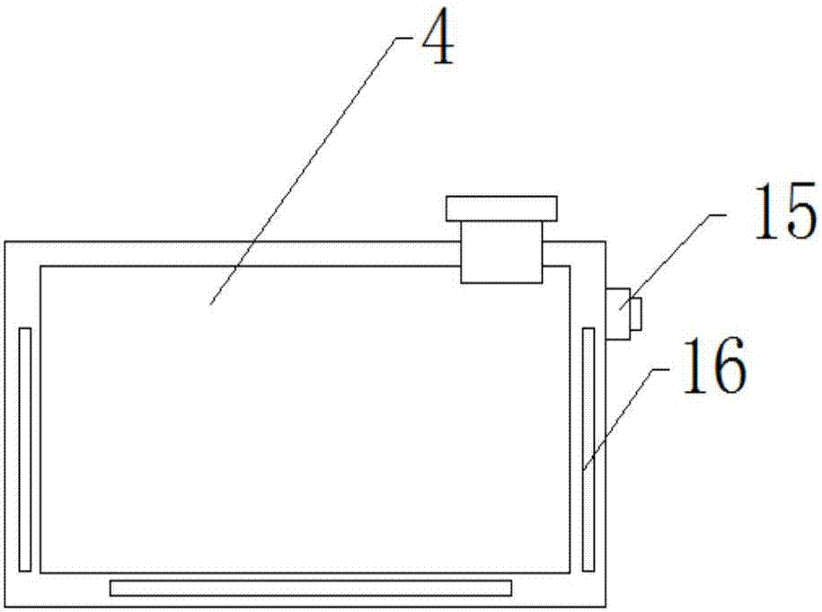
[0014] The technical solutions in the embodiments of the present invention will be clearly and completely described below in conjunction with the accompanying drawings in the embodiments of the present invention. Obviously, the described embodiments are only a part of the embodiments of the present invention, rather than all the embodiments. Based on the embodiments of the present invention, all other embodiments obtained by those of ordinary skill in the art without creative work shall fall within the protection scope of the present invention.

[0015] In the description of the present invention, it should be noted that the directions or positional relationships indicated by the terms "vertical", "upper", "lower", "horizontal" and the like are based on the directions or positional relationships shown in the drawings, and are only for It is convenient to describe and simplify the description of the present invention, rather than indicating or implying that the pointed device or eleme


PUM


Abstract

The invention discloses a plate gluing device, which comprises a main frame. The top of the main frame is sequentially provided with a gluing bin and a cleaning bin from left to right. A pressure roller is fixedly installed in the inner cavity of the gluing bin. The main frame is fixedly welded with a rubber groove directly below the pressure roller, and an upper rubber roller is installed in the inner cavity of the rubber groove. The upper rubber roller is directly opposite to the pressure roller, and the main frame is located in the rubber groove. The left and right sides of the frame are respectively horizontally aligned with a supporting roller group and a conveying roller group through the brackets, and a ventilation and cooling fan parallel to it is fixedly installed under the supporting roller group. An upwardly inclined scraping plate is welded, a glue storage box is installed on the top of the upper glue bin, and a motor is fixedly installed on the bottom leg of the main frame. The invention is easy to operate, can quickly apply glue to the board, and can quickly cool down the hot melt glue painted on the board, so as to increase the cooling rate and further improve work efficiency.

Description


Claims


Application Information

Patent Timeline
Owner LIANGXI HAOXING IND DESIGN OFFICE
Why Eureka
Try Eureka