Array substrate and detection method thereof and display device

An array substrate and substrate substrate technology, which is applied in optics, instruments, characters and pattern recognition, etc., can solve the problems of affecting the display effect of the display panel and the strong reflective performance of the metal light-shielding layer, and achieve the effect of reducing the impact and reducing the reflection.

Inactive Publication Date: 2017-12-01
BOE TECH GRP CO LTD
View PDF6 Cites 25 Cited by
  • Summary
  • Abstract
  • Description
  • Claims
  • Application Information

AI Technical Summary

Problems solved by technology

[0005] Embodiments of the present invention provide an array substrate, its detection method, and a display device, which are used to solve the proble

Method used


Image

  • Array substrate and detection method thereof and display device
  • Array substrate and detection method thereof and display device
  • Array substrate and detection method thereof and display device

Examples


Embodiment Construction

[0037] Aiming at the problem in the prior art that the display effect of the display panel is affected due to the strong reflective performance of the metal light-shielding layer, an embodiment of the present invention provides an array substrate, a detection method thereof, and a display device.

[0038] The specific implementation manners of the array substrate provided by the embodiments of the present invention, its detection method and the display device will be described in detail below with reference to the accompanying drawings. The thickness and shape of each film layer in the drawings do not reflect the real scale, and the purpose is only to illustrate the content of the present invention.

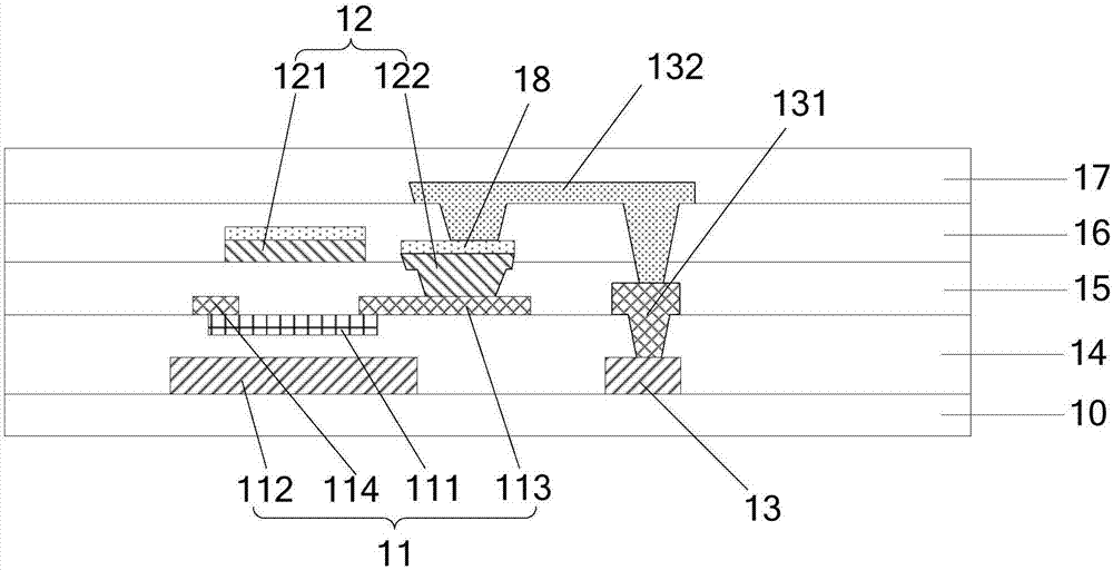
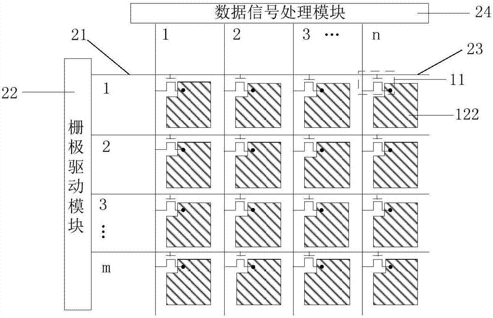
[0039] An embodiment of the present invention provides an array substrate, such as figure 1 As shown, it includes: a base substrate 10, a thin film transistor 11 located on the base substrate 10, such as a plurality of thin film transistors arranged in an array, and a photosensitive


PUM


Abstract

The invention discloses an array substrate and a detection method thereof and a display device. The array substrate comprises an underlayer substrate, a thin film transistor located on the underlayer substrate and a photosensitive layer located on the underlayer substrate; the photosensitive layer comprises a shading part, at least part of orthographic projection, on the underlayer substrate, of the figure of the shading part blocks the figure of an active layer of the thin film transistor, and the shading part is located on the side, deviating from a grid electrode, of the active layer of the thin film transistor. According to the array substrate, the shading part in the photosensitive layer is adopted for blocking the figure of the active layer, due to the fact that the photosensitive layer is illuminated with light rays, a photo-generated current can be generated, that is to say, the photosensitive layer can convert light energy into electric energy, the photosensitive layer has the certain light absorption effect, most of the light rays are absorbed by the photosensitive layer, light reflection of the shading part is reduced, and the influence on the display effect of the display device is reduced.

Description


Claims


Application Information

Patent Timeline
Owner BOE TECH GRP CO LTD
Why Eureka
Try Eureka