Double-shaft driving tundish tipping device

A dual-axis drive and bag tipping technology, applied in the field of iron and steel casting, can solve the problems of bag body distortion and deformation, and achieve the effect of hydraulic drive with large locking force, high safety factor, and reduced installation difficulty

Inactive Publication Date: 2018-01-09
孙宽
View PDF0 Cites 1 Cited by
  • Summary
  • Abstract
  • Description
  • Claims
  • Application Information

AI Technical Summary

Problems solved by technology

The traditional tundish is rotated by a single-side motor. When the tundish is filled with molten steel, the tundish is prone to distortion and deformation

Method used


Image

  • Double-shaft driving tundish tipping device
  • Double-shaft driving tundish tipping device

Examples


Example Embodiment

[0030] Embodiments of the present invention will be described with reference to the accompanying drawings.

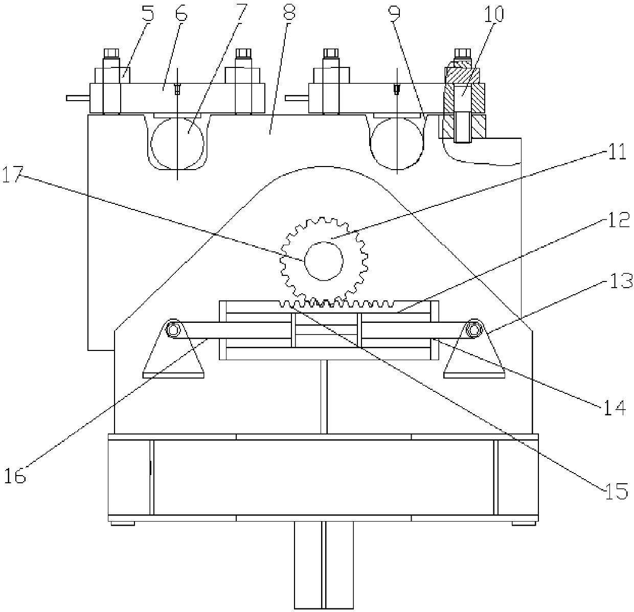
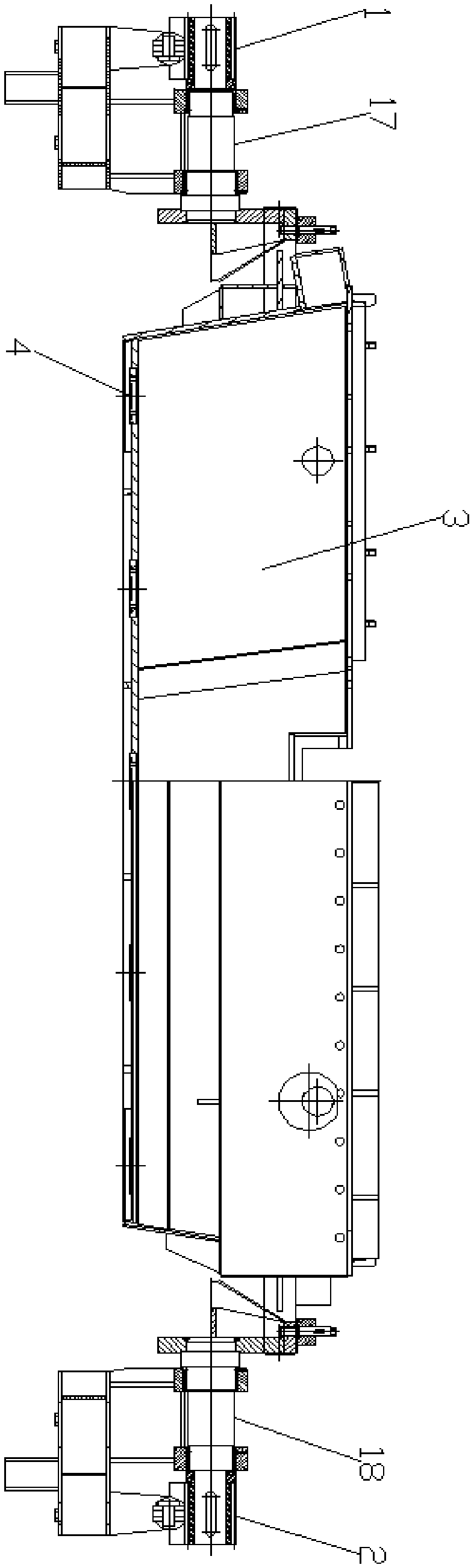
[0031] A dual-axis drive tundish tipping device includes a first drive assembly 1, the first drive assembly 1 includes a base 20, an oil cylinder support base 13 is installed on the base 20, and the oil cylinder support base 13 is fastened on both sides of the base 20 by bolts, It is connected with the first telescopic rod 14 and the second telescopic rod 16 of the double-rod oil cylinder 12 through the pin shaft 21. There are piston cylinders on both sides of the piston of the double-rod oil cylinder 12, which are driven by two-way hydraulic pressure. The rod 14 and the second telescopic rod 16 are hollow double rods, the cross section of the double rod cylinder 12 is square, and the rack 15 is installed on the surface of the cylinder through bolts; the length of the rack 15 is equal to the length of the double rod cylinder 12, and the double rod cylinder 12 The length re


PUM


Abstract

The invention provides a dual-shaft driven tundish tipping device, which belongs to the technical field of iron and steel casting. The positioning of the tundish is realized by the guide shaft and the guide groove, and then the compression of the guide shaft and the guide groove is realized by the fixed pressure plate and the locking bolt. The locking bolt is connected with the threaded hole of the tundish bracket through the threaded part, and the locking bolt is Partially wedged through wedges. When the tundish is overturned, one end of the first telescopic rod and the second telescopic rod of the double-rod cylinder is fixed. When the solenoid valve fills oil on one side and discharges oil on the other, the cylinder body of the double-rod cylinder pushes to one side, driving the rack to One side moves, and then the gear drives the first shaft and the second shaft to rotate to realize the flipping of the tundish. Compared with the single shaft drive, the dual shaft drive can prevent the twisting and deformation of the tundish during the flipping process, and the wedge is used as a fixed pressure plate When the locking part of the tundish is turned over, under the action of pressure, the wedge will be deeply wedged into the bolt, so as to avoid the fatigue failure of the pin and cause fracture.

Description


Claims


Application Information

Patent Timeline
Owner 孙宽
Why Eureka
Try Eureka