LED lamp processing mold

A technology of LED lamps and lamps, which is applied to lighting and heating equipment, lighting devices, light sources, etc., can solve the problems of low work efficiency and high labor cost, and achieve the effects of improved work efficiency, simple processing and manufacturing, and material saving

Active Publication Date: 2018-01-09
ZHEJIANG MEIKE ELECTRICAL APPLIANCE
View PDF7 Cites 0 Cited by
  • Summary
  • Abstract
  • Description
  • Claims
  • Application Information

AI Technical Summary

Benefits of technology

This patented technology allows for automated assembling of lamps during production while minimizing any impacts or vibrations caused due to their movement over long distances through rails. By utilising specialized parts called rings made up of rubber-like material (rubbers) instead of metal balls used traditionally, it reduces wear between these components and improves durability compared to existing methods such as rolling them onto steel wheels. Additionally, there're also fewer workers needed per unit area, saving money and making maintenance quicker. Overall, this innovation simplifies the entire process of producing high-quality light sources more efficiently.

Problems solved by technology

This patented technical problem addressed in this patents relates to improving the process for attaching lighting devices (LED lamps) onto printed circuits during production processes due to their large size and complexity. Current methods are time-consuming and require manual effort which can increase costs compared with automated systems that use robots or other tools instead of human operators.

Method used


Image

  • LED lamp processing mold
  • LED lamp processing mold
  • LED lamp processing mold

Examples


Embodiment Construction

[0025] In order to enable those skilled in the art to better understand the solutions of the present invention, the technical solutions in the embodiments of the present invention will be described clearly and completely in conjunction with the accompanying drawings in the embodiments of the present invention.

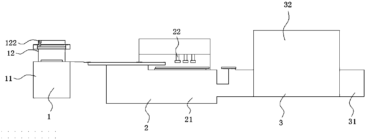
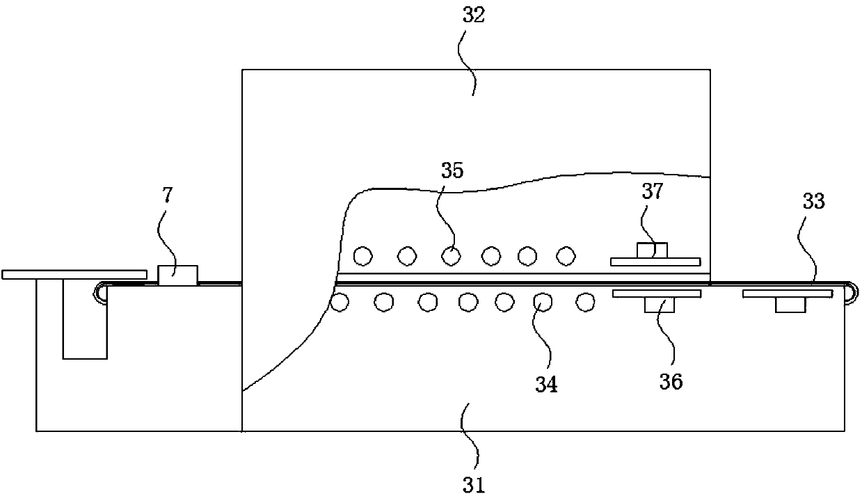
[0026] Such as Figure 1-10 As shown, an LED lamp processing mold includes a paste application mechanism 1, a lamp sheet assembly mechanism 2, a drying mechanism 3, and a conveying track 4 provided between the paste application mechanism and the lamp sheet assembly mechanism; the FPC circuit board first After the solder paste is projected on the pasting mechanism, it is transported to the lamp assembly mechanism through the conveying track. After the LED lamp is assembled in it, it is sent to the drying mechanism for drying to realize the automatic assembly of the LED patch lamp Specifically, the lamp assembly mechanism 2 includes a mobile workbench 21 and a lamp stamping co


PUM


Abstract

The invention discloses an LED lamp processing mold which comprises a paste smearing mechanism, a lamp sheet assembly mechanism, a drying mechanism and a conveying rail arranged between the paste smearing mechanism and the lamp sheet assembly mechanism. The lamp sheet assembly mechanism comprises a movable working table and a lamp sheet stamping column matched with the movable working table; the movable working table comprises a bottom plate capable of moving front and back as well as left and right, a movable rail capable of moving up and down and arranged on the bottom plate, a first drivingpiece used for driving the bottom plate to move front and back, a second driving piece used for driving the bottom plate to move left and right and a third driving piece used for driving the movablerail to move up and down; and a first stopping device is arranged at the tail of the conveying rail, and a second stopping device is arranged at the tail of the movable rail. According to the LED lampprocessing mold, automatic assembly is achieved on a lamp sheet through the lamp sheet stamping column, and the working efficiency is improved to a great extent; and synchronous conducting can be achieved on feeding and discharging of the movable rail, no intermittence exists between feeding and discharging, and the efficiency is higher accordingly.

Description


Claims


Application Information

Patent Timeline
Owner ZHEJIANG MEIKE ELECTRICAL APPLIANCE
Why Eureka
Try Eureka