Insulating blocking head with sensing function

A technology of functions and plugs, which is applied in the field of insulating plugs with sensing functions, can solve the unfavorable problems of miniaturization, complicated wiring, and heavy weight of the ring main unit, and achieve the effects of light weight, small size, and convenient use

Inactive Publication Date: 2018-03-09
江苏科兴电器有限公司
View PDF8 Cites 0 Cited by
  • Summary
  • Abstract
  • Description
  • Claims
  • Application Information

AI Technical Summary

Problems solved by technology

However, most of the existing electromagnetic transformers for ring network cabinets are complicated in wiring, and when connected to the ri

Method used


Image

  • Insulating blocking head with sensing function
  • Insulating blocking head with sensing function
  • Insulating blocking head with sensing function

Examples


Embodiment Construction

[0012] Further description will be made below in conjunction with drawings and embodiments.

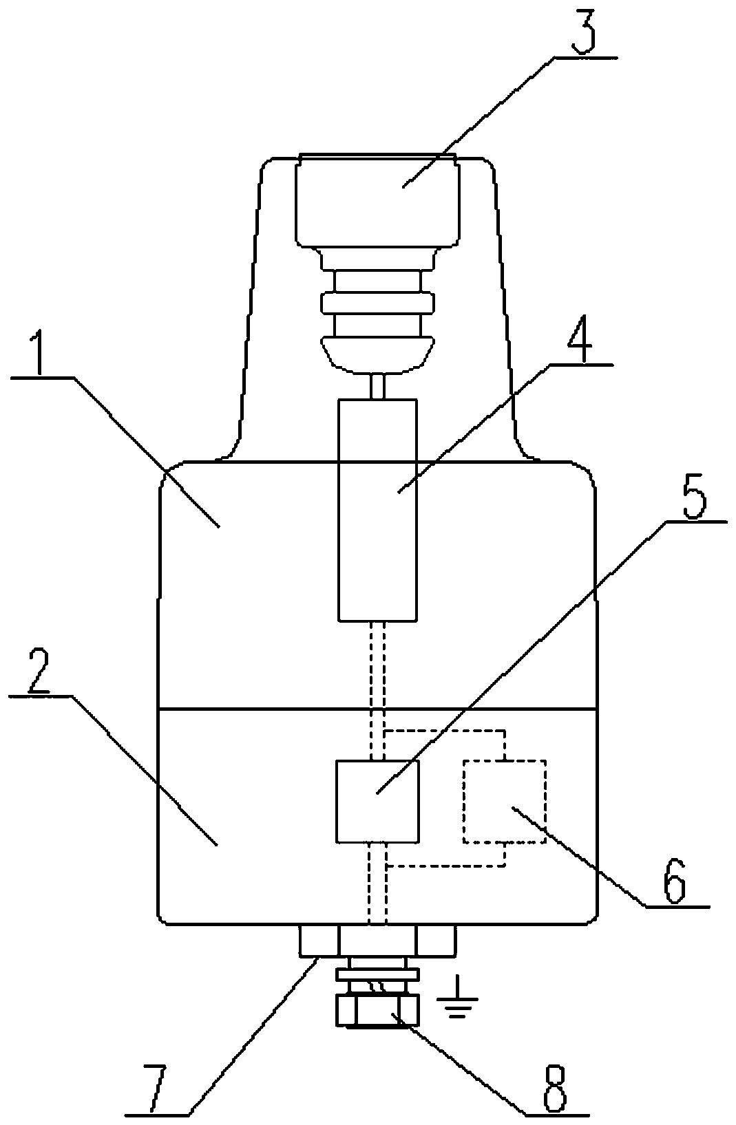
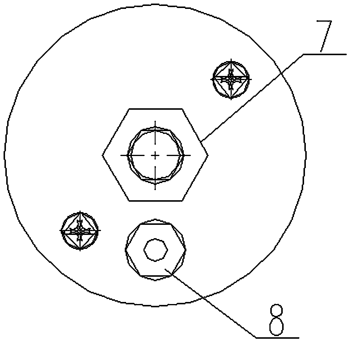
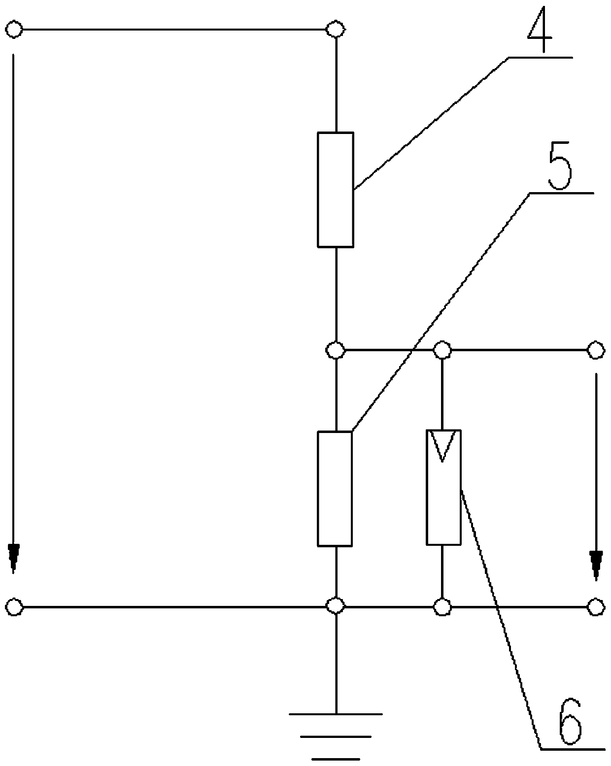
[0013] figure 1 , 2 As shown: an insulating plug with sensing function includes epoxy resin casting body 1, metal shielding case 2, high voltage terminal 3, high voltage resistor 4, low voltage resistor 5, varistor 6, outer hexagonal boss 7, Waterproof joint 8. The high-voltage terminal 3, the high-voltage resistor 4, the low-voltage resistor 5, and the varistor 6 are integrally molded through the epoxy resin casting body 1. The high-voltage terminal 3 is set at the upper conical insertion end of the epoxy resin casting body 1. The high-voltage resistor 4 and the low-voltage resistor 5 are connected to the waterproof joint 8 on the lower surface of the epoxy resin cast body, the low-voltage resistor 5 is connected in parallel with the varistor 6, and the lower part of the epoxy resin cast body 1 is encapsulated in the metal shielding case 2, and the metal shielding case 2 The center o


PUM


Abstract

The invention relates to an insulating blocking head with a sensing function. The insulating blocking head comprises a metal shielding hood shell, a high voltage terminal, a high voltage resistor, a low voltage resistor, a varistor and a waterproof connector, the high voltage terminal, the high voltage resistor, the low voltage resistor and the varistor are integrally pour-molded by an epoxy resinpouring body, the high voltage terminal is arranged on the conical inserting end of the upper portion of the epoxy resin pouring body, the high voltage terminal passes through the high voltage resistor and the low voltage resistor in sequence to be connected with the waterproof connector on the lower end face of the epoxy resin pouring body, the low voltage resistor is in parallel connection withthe varistor, the lower portion of the epoxy resin pouring body is encapsulated in the metal shielding hood shell, and an outer hexagonal boss is arranged in the center of the lower end face of the metal shielding hood shell.

Description


Claims


Application Information

Patent Timeline
Owner 江苏科兴电器有限公司
Why Eureka
Try Eureka